The REX (ZANUSSI) SUPERAUTOMATICA 290 washing machine
describes a 5kg front loading (HEAVVVVVY) washing machine, with a rotary drum,
comprising a chassis that supports a cylindrical washing tub inside
which there is mounted a rotary inox steel drum with a horizontal axis.
The washing tub intended to contain a liquid soap, and a drum with
perforated walls for containing the clothes to be washed, and which is
rotationally mounted inside the washing tub and driven by an electric
motor to rotate in both directions with respect to an axis that is
substantially horizontal or slightly tilted with respect to a horizontal
direction. Generally, this type of machine can rotate the drum at a
fast speed in order to drain the clothes contained inside by spinning
them.
REX (ZANUSSI) SUPERAUTOMATICA 290 ELECTROMECHANICAL INTERLOCK FOR LAUNDRY APPARATUS:
Interlock for the door of a clothes washing machine or the
like. The interlock is characterized by the provision of a
solenoid-actuated door lock, which

solenoid is operatively connected to a
source of electrical power by means of a condition responsive structure
and also by a manually operable switch. Energization of the solenoid
serves to unlatch the door lock to thereby provide a "fail-safe" device,
which can only be opened when the machine is not operating and by
actuation of the manual operable switch.
1. Door interlock for a clothes washing machine having an access door to the washing apparatus and suitable circuitry including a timer for controlling the operation thereof, said interlock comprising:
2. The door interlock of claim 1 wherein said fluid pressure switch is open whenever said washing machine contains washing fluid.
Description:
BACKGROUND OF THE INVENTION
This invention relates, in general, to laundry apparatus and, more particularly, to door lock structure therefor.
It is well known that commercial washing machines of the tumbler type utilize water which exceeds the level of the machine opening. This means that if the door is opened prematurely, a person could be scalded by the extremely hot water. There are also other hazardous conditions which exist, for example, during the water extraction part of the cycle when accessibility to the interior of the machine is prohibitive.
Accordingly, it is the general object of this invention to provide a new and improved clothes washing machine.
It is a more particular object of this invention to provide, in a clothes washing machine, an electromechanical door interlock, the purpose of which is not frustrated by an electrical power failure.
Another object of this invention is to provide a door lock for a washing machine which cannot be unlatched during operation of the machine or at preselected times during the operation of the machine.
BRIEF SUMMARY OF THE INVENTION
Briefly, the above-cited objects are accomplished by the provision of a lock having a latch and catch arrangement wherein the latch is spring biased into a door locking position. A solenoid is provided for overriding the spring through the pivoting of a lever in response to energization of the solenoid. In order to provide a safety feature which prevents unlatching of the lock at any time during operation of the machine or during preselected times during the operation thereof, a timer-actuated switch is provided which is opened at the preselected times, consequently, the solenoid cannot be energized. A pushbutton switch is also provided which switch cooperates with the timer-actuated switch to permit energization of the door lock solenoid, closure of both switches, simultaneously, being required before the door can be opened.
In a modified form of the invention, a pressure-actuated switch is combined in circuitry with the timer-actuated and pushbutton switches such that the door unlock solenoid cannot be energized while water remains in the machine, even though operation of the machine has terminated.
REX (ZANUSSI) SUPERAUTOMATICA 290 TIMER HOLZER AT96 APPARATUS FOR CONTROLLING FULLY AUTOMATIC WASHING MACHINES:
Walter Holzer, Schutzenrain, Meersburg
(Bodensee), Germany.

The invention relates to an apparatus for controlling
fully automatic washing machines wherein cam operated
switches are used for this control.
Control units for controlling fully automatic washing
machines are known in which cams moving in adjacently
disposed concentric tracks operate resilient contact levers
mounted at one end.
The disadvantage’ of this arrangement consists in the
great difficulties encountered _in manufacture, since if the
movable contacts are disposed in close formation it is
difficult to maintain thevminimum current leakage path.
Moreover, it is necessary for the control discs to be accu-
rately mounted and machined to present additional diffi-
culties during manufacture.
It is an object of this invention to eliminate the dis-
advantages of these known arrangements by constructing
the control disc with contacts and housing so that the
metal parts can be produced by means of non-cutting
operation and the housing and control disc are made of
pressed material such as plasters. A further object is to
provide a mounting of economical and simple design, but
sufliciently accurate to insure a high degree of operational
safety and accuracy particularly in the case of washing
machines where much vibration occurs.
The solution of the problem ac

cording to this inven-
tion comprises resiliently.mounting the upright rigid con-
tact arms in semi-open bearings and the rigid control disc
is adapted to run resiliently on balls which support the
control disc over the greater part of its diameter.
In accordance with this feature, the contact arms are
not rigid but resilient. The control disc is also resilient.
The accuracy in the co-operation between contact levers
and control disc is achieved by a ball mounting, i.e. balls
running in a cage, .and.the control disc is resiliently urged
against theseballs.
It is then unnecessary for the control disc to be mounted
in the exact center. The control disc is externally re-
tained so that contact surfaces concentric with one an-
other are formed in.a satisfactory manner.
Withreference to achieving large insulation air gaps,
a further featu

re consists in the fact that the circular
control disc is mounted on a square base plate. The ad-
jacently disposed contact arms extend in groups parallel
to the edges of the base plate, contact arms running on
adjacent cam tracks each being offset by 90°.
By means of _this arrangement, the control disc is
loaded uniformly and symmetrically by the contact arms,
and the operation of the contact arms is such that there
are always adequate insulation air gaps. The spacing
of the adjacently disposed contacts no longer determines
the insulation air gaps but the contacts are arranged olf-
set and the air gap corresponds approximately to a quarter
of the diameter of the control disc. This air gap is
always sufficiently great, hence affording a considerable
reaction in the cost of manufacture.
With reference to the contact arms, it is important for
the contact arms to be mounted at one end to have the
movable contact thereon adjoining the edge transmitting
the switching movement. The movable contacts are
pressed by a spring against a fixed stationary contact
mounted in a vertical guide for. the contact arm.
The contact arm is thus rigid and engagement of ‘the
contacts is not made by bending the contact lever, but
by spring-loading the rigid contact lever at a selected
point. The movable contact itse

lf is not mounted on the
tip of the contact lever, but at a different point inwardly
of the cam follower on the end of the arm so that when
the contact arm is urged upwardly by a cam of the con-
trol disc against the spring which acts on the contact arm,
contacts are opened in a positive manner. The spring
rapidly closes the contacts when the contact arm leaves
the cam on the control disc.
A further possible modification consists in the fact
that centrally pivoted contact arms extend radially with
respect to the control disc and that the control disc has
a guide axle on the side opposite to the feeler levers.
It is thus possible for the contact arms to be constructed
as rocker arms having a common mounting in the center
and making contact on both ends. It is also possible,
of course, to use two-armed arms instead of one-armed
two-ended arms, so that the contacts may be moved either
in conjunction with or independently of the contact on the
opposite end of the contact arms.
A convenient mounting for the contact arms consists
in the fact that semi-open bearin
gs of the contact arms
consist of a notch with a counter bearing. The springs
loading the contact arms are arranged a short distance
from the mounting points and are supported on the
housing.
The use of semi-open bearings makes it possible for
starnpings to be used, the pressure of the spring forcing
the lever into the bearing providing sufficient accuracy
with regard to the mounting.
A convenient arrangement for simple connection in a
washing machine consists in the fact that all contact--
levers terminate on one side of the housing in soldering
lugs or terminals or plug connections.
‘With the complicated structure of control circuits in
washing machines in particular, it is important for the
terminals to be readily and simply accessible.
This object is substantially achieved by means of ter-
minals mounted on one side of the housing.
It is also convenient for all contact arms, fixed con-
tacts, and the control disc to be accommodated in a’
closed housing of plastic material, the drive for the con-’
trol disc entering on one side of the housing, while on
the other side all terminals are accessible from the outside.
This design is operationally very safe, since the sensi-
tive parts, the cam tracks and contac
ts, the balls, and
the springs are protected from accidental contact and dirt
by the _enclosing housing. Only the contact terminals
are located on one side of the housing, while on the oppo-
site side the shaft for the connection of the drive projects
therefrom.
Additional features comprise arranging balls in the
housing for supporting the control disc and, if necessary,
guided in a cage, while the springs urging the disc against
the balls are supported in the housing.
This design involves the lowest conceivable effort in
manufacture because it is not nece
ssary for a cage with
balls to be placed on a base plate, since a groove for
the balls to run in has already been pressed in the base
plate. The control disc is placed on these balls and
the housing cover, on which the contacts with the springs
are situated, is then placed in position. When the hous-
ing cover and base plate are secured or screwed together
there is automatically acthieved the highest possible ac-
curacy, since, particularly from the point of View of
pressing technique, it is always insured that the distance
from the inside of the housing cover, to the outer surface
thereof remains constant, i.e. it is now possible to mass
produce a component having a high degree of accuracy
and operational reliability.
The invention will be described further, by way of
example, with reference to the accompanying drawings,
in which:
FIG. 1 shows diagrammatically a plan View of a con-
trol disc with base plate and Contact arms arranged
thereon;
FIG. 2 shows diagrammatically in side elevation the
mounting of the contact arms and the contacts;
FIG. 3 shows diagrammatically the arrangement of
these components in a housing; and
FIG. 4 is a detail of the spring-loading device of the
contact arms.’ ‘
The control disc 2 in FIG. 1 is mounted on a base plate’
1, which is conveniently of square shape, this control disc
2 being maintained in an approximately central position
by a spindle 3 passing through a bore in the base plate
1. The accuracy of operation of the control disc, how-
ever, does not depend upon the closeness of fit of the spin-
dle 3 in the housing 4 or the base plate 1.
The control disc 2 is provided in a known manner with
concentric cam tracks or paths 5. It is thus possible for
ten or twenty such cam tracks to be arranged in close for-
mation, i.e. with a clearance of one or two millimeters.
The cam tracks are indicated only by means of circles.
Within these cam tracks there are formed elevations and
depressions in which the contact arms 6 engage with their
cam followers "7, the contact levers 6 being thus moved
up and down in the direction of the arrow 8. By this
movement, the contacts 9 of the contact arms are either
disengaged from the fixed contact 10 or, when the cam
allows by means of a corresponding depression, pressed
against each other by the contact arm spring 11.
The contact arms themselves are prevented from tilting
by a vertical guide 12, and on this guide is located a fixed
contact 10. A notch 13 and the corresponding projec-
tion 14 from a semi-open bearing, such semi-open bear-
ylllg being fixed on the housing and provided for example
with a metal lug or terminal 15 as soldering lug, or the
whole component may be made of metal. The fixed
contact 10 receives its electrical connection at the solder-
ing lug 16.
The contact arms 6 are combin

ed in groups in such a
way that in one group with arms numbered 17, 18, 19, 20
another group with arms numbered 21, 22, 23, 24, and
subsequent groups with arms numbered 25, 2/6, 27, 28
and 29, 30, 31, 32 the differently numbered contact arms
are all situated on different cam tracks. In accordance
with the control circuit, the following contact arms run
in adjacently disposed contact tracks: 17, 21, 25, 29 or
18, 22, 26, 30 or 19, 23, 27, 31 or 20, 24, 28, 32. It will
thus be apparent that the insulation air gap between two
adjacent contact arms thus amounts to approximately a
quarter of the circle, which is an ample gap.
It is evident from FIG. 3 that the balls 33 which are
provided and which, for example, are guided in a cage 34
or corresponding grooves in the base plate 1, insure that
when the base plate 1 has been screwed together with the
housing 4 at the mounting edge 35, the critical distance
36 between the inner surface of the housing and the in-
ner surface of the base plate 1 remains constant. A spring
37 also serves to press the control disc 2 against these
balls. It can also be seen from FIGURE 3 that the ter-
minals are all provided on one side, only the metal lugs 15
and not the soldering lugs 16 being available in FIG. 3,
while on the other side it is possible for the drive to be
connected.
FIG. 4 also shows another possibility of mounting the
contact arms. In the housing 4, integral with the metal
part which pivots about the projection 14, i.e. forms open
bearings for the notch 13 of the contact arm 6, there is
provided a guide member 38, which terminates in a metal
lug 39 on the housing. The metal lug 39 extends parallel
to the metal lug 15 and facilitates the connection of paral-
lel plug sockets. This guide member 38 has a recess 4-0.
This recess 40, together with the recess 41 in the contact
arm, forms the guide for the contact spring 11. The con-
tact spring 11 is now situated parallel to the contact,
which is formed by the contact surfaces to the notch 13
and the projection 14, so that these contact surfaces are
kept apart by means of the parallel disposed spring.
There has also been obtained a closed circuit between
the contact spring 11 and the mountin
g of the notch 13
on the projection 14. This is particularly convenient
when recesses for the guide of the spring loading the con-
tact arm are provided in the housing and in the contact
arm, the guide member accommodated in the housing
forming a metallic live conducting unit with the semi-
open bearing and the spring which participates in the cur-
rent supply.
It is important for the guide member to terminate in
a metal lug 15 or metal lug 39 in the housing.
Suitable fields of application of -the present invention
are all cases wherein it is intended to use concentric cam
tracks for controlling fully automatic washing machines,
and where it is necessary to obtain operational reliability
and a cheap method of manufacture. -
What I claim is:
1. A device for controlling autoznatic washing ma-
chines, comprising: a control disc; a plurality of concen-
tric cam tracks on a face of said disc and having cam sur-
faces transverse to said disc; a plurality of fiat contact
arms corresponding to the plurality of said cam paths,
said arms being arranged in groups around the center
of the disc with the arms pertaining to each group being
disposed in parallel relationship and arranged in tangen-
tial direction with respect to said disc, the fiat surfaces
of said arms being perpendicular to the plane of exten-
sion of the disc; a guide member for each of said contact
arms and extending also transversely to said disc; a sta-
tionary contact on each of said guide members; a cam
follower on a first end of each contact arm and engage-
able with a corresponding cam track whereby cam fol-
lowers engaging adjacent tracks pertain to different
groups; means for pivotally mounting the other end of
each contact arm, the pivot axis for each contact arm
extending in the plane of extension of said disc and trans-
versely to the plane of extension of the flat c
ontact armj
a movable contact at said first end of said contact arm
and engageable with said stationary contact; spring means
acting against said contact arm to urge the contacts into
engagement; and means for supporting said disc near its
circumference.
2. A device, as claimed in claim 1, wherein said mount-
ing means comprises a rounded support with a groove
in said contact arm other end engaging said rounded sup-
port, said spring means being spaced from said mount-
ing means.
3. A device, as claimed in claim 1, and further com-
prising terminals for said stationary and movable con-
tacts with said terminals being located on one side of
said device.
4. A device, as claimed in claim 1, and further com-
prising a housing for said device, terminals for said sta-
tionary and movable contacts projecting from one side of
said housing and means for driving said control disc on
the opposite side of said housing.
5. A device, as claimed in claim 1, said supporting
means comprising a plurality of ball bearings support-
ing the other face of said control disc, a cage retaining
said ball bearings, and spring means urging said control
disc against said ball bearings.
6. A device, as claimed in claim 1, and further com-
prising a housing, there being means in said housing de-
fining recesses, there being opposing and cooperating re-
cesses in said contact arms, said spring means being posi-
tioned within pairs of cooperating recesses, said recess de-
fining means being connected to said mounting means and
forming with said spring means a current conducting unit.
7. A device, as claimed in claim 6, and comprising a
terminal on each recess defining means and extending out-
wardly of said housing.
8. A device, as claimed in claim 6 and further compris-
ing terminal pins extending from said recess defining
means and the mounting means connected thereto to form 5
a tubular contact.
9. A device, as claimed in claim 5, wherein said ball
bearings engage said control disc adjacent the outer pe-
riphery thereof.
10. A device, as claimed in claim 1, with said cam tracks 10
extending over the entire face of said control disc.
REX (ZANUSSI) SUPERAUTOMATICA 290 TIMER HOLZER AT96 Driving means of an impulse device and stepping mechanism for program contact:
The invention relates to a driving apparatus for a program control device for washing machines having a motor
driven pulse producing device or timer and a motor driven
step switching ‘program contact control device.
In the usual arrangement the -pulse device furnishing
timed pulses for the stepping of a program switch, andthe driving means for the program contacts each have a
The separate motors were a necessity
since the pulse device must function at precise intervals,

 thus requiring a motor with highly constant speed, while
. the stepping of the program contacts in intermittent service
requires an asynchronous motor, i.e., a motor with
a high torque. This motor, as a rule, does not have the
constant speed necessary for synchronous operation.
Further disadvantages of using two motors include the
increased
probability of breakdown, the need for more space, and the increased
production costs. The object of this invention is to avoid these
disadvantages and to employ a single motor for the function usually
carried out
by two. Nevertheless, the same advantages must be
retained in respect to versatility and further requirements for the
precise functioning of the impulse deviceand the stepping device for the
program contacts.
According to one aspect of the invention in a preferred
embodiment thereof it is suggested to employ a single
motor for driving in steps a rotatable program control or
switching device as well as a timer or pulse control; the
motor has an axially displaceable rotor being geared to
the step control only in one position thereof.
Another feature of the invention is a cam disc rotating
together with the program control and temporarily inter-
rupting a link or ‘driving connection or coupling within the
gear transmission driving the pulse control so that the
latter can return to zero or initial position. Another
feature of the invention is a spring biased gear or clutch
governing the link between rotor and program control;
the spring bias is overcome by an electric control shifting
the rotor in=to driving engagement with the program con-
trol, while the electric control is disabled by the‘ program
control itself after one step, and then the spring shifts the
rotor back whereb y the latter is disengaged from the pro-
gram control.
In accordance with this kind of design, a motor with a
specially built coupling is used to ensure that both the
impulse device and the stepping device for the program
contacts return independent of one another to their initial
positions after the conclusion of a pulse or a step.
A motor which is specially suited for the simultaneous
drive of the impulse device and the stepping of the pro-
gram contacts and has a shiftable armature in slidable
direction, so that the sliding armature through poles functions as
a synchronous motor in one axial position and as
an asynchronous motor in a second position axially dis-
placed from the first mentioned position.
This arrangement can be considered the ideal solution,
since on the one hand it ensures absolute precision of
the pulse transmission, and on the other hand it pro-
vides the greatest amount of torque for the stepping of the
program contacts. In- accordance with this construction,
the drive can -be shifted from impulse device to program
contacts in merely using control currents. Not even a
special control solenoid, nor any other kind of intermedi-
ary is then necessary. There may be provided manually
operated contacts, operating together with the program
contacts, since when the predetermined position is reached,
it is by-passed because the automatic cut-out contacts of’
the drive motor are bridged.
This arrangement permits the arbitrary exclusion or
bypassing of whole program sections in order to change
the wash-program. We are dealing here with rapid pre-
selection.
While the specification concludes with claims particularly
pointing out and distinctly claiming the subject matter which
is regarded ‘as the invention, it is believed that
the invention, the obyects of the invention, and further
objects and advantages thereof, will be better understood
from the following description taken in connection with
the accompanying drawing. in which:

FIG. 1 shows schematically the application of,one
motor to drive a pulse device as well as a stepping device,
using a motor which functions alternately as a synchronous
or asynchronous rotor.
fig 2 shows one position of coupling shown in FIG. 1 in action.
FIG. 3 shows the disengaged position of the coupling in FIG. 1 in action.
FIG. 4 shows a side view of the wheels in FIG. 2.
FIG. 5 shows one possible arrangement of a contact
system of a pulse device including an automatic Cut-out or
self-interruption mechanism. ‘ .
FIG_. 6 shows a sliding or axially displaceable rotor
operating upon a specific mechanical coupling, and
FIG. 7 is a modification of the device shown in FIG. 6.
FIG. shows one possible construction in an arrangement
in which a single motor operates a pulse device as well
as the stepping of program contacts over a coupling._ In
FIG. 1 a. pulse contact system, consisting of contacts 1,
2 and 3, is driven by motor 4 having an axially -displace-
able rotor 5 with shaft 6. Contacts 1, 2 and 3 are op-
erated upon by the following intermediate elements:
Armature rotor 5 has a pinion 7 on its shaft 6, which
together _with its gear wheel 8 and a pinion 9 drives an
intermediate wheel 10 having pinion 10 which in turn
drives a gear ‘wheel 12. Gear wheel 12 is secured to
shaft 13 carrying a cam disc in «which directly operates
contacts 1, 2 and 3. _Contacts 12 and 3 «are closed in
sequence when_ cam disc 14 is turned. The closing of
these_contacts in sequence may also be used to start a
stepping of switching disc 15, which, in «turn, operates
program contacts 19, as well as the other contactsnot
shown. This will be described below. .
In accordance with the principles of the invention, the
cam disc 14 is driven via a

coupling formed by the in-
termediate wheel 10 and its pinion 11. This pinion 11
can‘be disengaged from gear wheel 12. When pinion 11
is disengaged, spring 16 recoils by rotation gear wheel 12,
shaft 13 and cam disc 14 back into -their initial or’ zero
position. “
The stepping of switching disc 15 is produced by motor
ft by means of other intermediate elements, but disc 15
1S not always coupled drivingly to member 4. Power
transmission is achieved in the following manner and by
means of the following elements. There is provided an
electrical resistor 17 connected in series in the lead-in
wire to motor winding 18.
Resistor 17 can be over-bridged by contacts 26--27.
Armature or rotor 5 moves into the position indicated
by the dotted lines under the influence of the increased
magnetization. Increased magnetization occurs when re-
sistor 17 is short-circuited. When rotor 5 is in the “dot-
ted” position pinion 7 is engaged with gear wheel 20
havinga pinion 20’. Pinion 20’ meshes with a drive
Wheel 21. Drive wheel 21 is integral with or secured
to cam discs 22 and 23. Cam disc 22 is depicted in
FIGS. Disc 23 is eccentric as shown in FIG. 4. Ec-
centric disc 23 and disc 27 is keyed onto hollow shaft
24 receiving shaft 13. Drive wheel 21 drives switching
disc 15 for program contacts 19, eventually over inter-
mediate elements 25.
Cam disc 22 operates contacts 26 and 27 bridging
resistor 17 during any one step, until cam disc 22 has
returned to its initial position and opened contacts 26
and 27 by means of recess 31. In that way resistor
17 is placed again in series circuit connection of motor
4. In this instance armature or rotor 5 is forced back
into its initial position by spring 28.
During one revolution of cam disc 22, corresponding
to one step of switching disc 15, the eccentric disc 23
temporarily disengages intermediate wheel 10 and pinion
11 from gear wheel 12. This operation will be compre-
hended in connection with FIGS. 2 and 3. In FIG.
2 pinion 11 is engaged with gear wheel 12 and pulse
contacts 1, 2 and 3 are then driven by cam disc 14.
In FIG. 3 eccentric disc 23 is in a position occurring
during the stepping (rotation of elements 22, 23 and
24) that an intermediate Wheel 29 (omitted in FIG.
1) together with shaft 30 carrying intermediate wheel 10
and pinion gear 11, are raised. In this position pinion
11, and gear wheel 12 are disengaged and spring 16 re-
coils gear wheel 12, shaft 13 and cam disc 14 by ro-
tation, into their initial position, which is the initial po-
sition of the timer or pulse device. 2
FIG. 4 shows the gearing in FIGS. 2 and 3 from a
side view. It is particularly important that the axial
shift needed to engage pinion 7 and gear wheel 20 is
used to change the running characteristics of motor 4.
When rotor 5 is in the position shown in the drawing,
it functions, in the presence of poles, as a synchronous
motor which, with a small load, operates with the great-
est precision. In the position indicated by the dotted
lines, corresponding to an increased magnetization cur-
rent, the motor functions as an asynchronous motor and
is capable of producing a relatively high amount of
torque. This is necessary in order to operate switching
disc 15 and a number of program contacts 19.
This arrangement described thus far operates in the
following way. First motor 4 runs as a synchronous
motor and drives cam disc 14 out of its initial position so
that contacts 1, 2 and 3 be closed after predetermined
times. This is the timer action o
f the pulse device. The
contacts may also effect an increase of the magnetization
current over a pre-selector not appearing in the drawings,
over-bridging resistor 17. The increased magnetization
current pulls rotor 5 into the position indicated by the
dotted lines. ‘Now pinion 7 engages wheel 20 and switch-
ing disc 15 is rotated with a high amount of torque; c-am
discs 22 and 23 follow this rotation. Cam disc 22 oper-
ates contacts 26 and 27 as stated. These contacts 26
and 27 maintain the increased magnetization current by
continuing the bridging of resistor 17 until cam disc 22
has revolved completely. Thus, resistor '17 remains out
of circuit even if contacts \1—3 are opened by the re-
coiling of cam disc 14 described above. Cam disc 22
insures that a complete revolution of elements 22 and
23 is carried out before contacts 26 and 27 are opened
so that a complete step of switching disc 15 takes place
with motor 4 running as a synchronous motor. When
recess 31 opens contacts 26 -and 27, rotor 5 returns to
its initial position due to the decreased magnetization
current. Pinion 7 then again is disengaged from gear
wheel 20, and the movement of the switching disc 15
and of cam discs 22 and 23 ends.
-FIG. 5 furthermore shows a simplified design of the
arrangement depicted in FIG. 1, whereby both cam disc
14 and cam disc 22 operate the same contacts 26 and 27.
The arrangement operates in the following manner:
After a given period of time, shoulder 32 of cam disc
14 reaches contact 26 and bends it so as to connect with
contact 27. In that way only contacts 26 and 27 serve
to shunt resistor 17 so that the magnetization current of
motor 4 is increased. Thereafter cam disc 22 commences
to run thereby holding contacts 26 and 27 in a closed
position for «a complete revolution of disc 22. ’
During the revolution of cam disc 22, corresponding
to a step of switching disc 15, the coupling, consisting of
intermediate wheel and pinion 11 is disengaged and cam
disc 14 is recoiled back into its starting or zero position
as outlined above. ‘Independent of that, cam disc 22
affixed to hollow shaft 24 completes its revolution until
contacts 26 and 27 pass through recess 31 and open
with the effect outlined above. One reservation must
be made for this arrangement, namely that only one
impulse time can be controlled.
FIG. 6 shows a particularly reliable construction of the
coupling between rotor 5, the gearing for the pulse device
and the stepping device.
are designated alike. The advantage of this arrange-
ment lies in the fact that pinion 7 always remains engaged
with gear wheel 8, even when rotor 5 is shifted. Power
transmission for the stepping device is effected over a
clutch 52 co-operating with -mating claws 53. Pinion 7
continuously drives the pulse device via gear wheel 8
and pinion 9 and the elements shown in FIG. 1 for drivingly
connecting pinion 9 to disc 14.
Upon increase of its magnetization current rotor 5
is shifted in the direction of arrow 54 and engages clutch
52 with mating claws 53 over a double-armed lever 55
and a transmission member 56. Now power is trans-
mitted from pinion 7 over gear wheel 8, clutch 52 and
a pinion 57 to a gear wheel 58 and thereby over inter-
mediate elements to switching disc 15. This drive also
operates cam disc 22 for the automatic cut-out.
Upon decrease of the magnetization current after a
completed step, -a spring 59 resiliently connecting clutch
52 and claws 53 brings all the parts of the coupling into
their initial i.e. disengaged position. Also spring 59
forces rotor 5 back into the position where it runs as
synchronous motor. This is also effected by lever 55.
The particular advantage of this arrangement not only
lies in the fact that pinion 7 always remains engaged
with gear Wheel 8, but also a
certain shock-protection
is gained because transmission member 56 has a pre-
determined mass relationship to the rotor. This ar-
rangement is particularly advantageous when rotor 5
has twice the mass of member 56. In this case, sym-
metric acceleration relations result, because the accelera-
tion forces of rotor 5 and of transmission part 56 can be
balanced in their direction by means of the double—armed
lever 56, in suitably selecting the distances of the action
points of lever 56» from pivot 60. Here, the static effect
of counter-spring 59 is taken into consideration.
FIG. 7 shows another design of the coupling between
rotor 5 and the step switching device. In this case, there
is provided a leaf spring 61 which grips both rotor shaft
6 and transmission member 56. In this arrangement also,
there is a great independence of acceleration forces.
The invention can be used in all cases where one desires
to construct a motor and its coupling in such a way
that in one position of the coupling, with a very small,
load, transmission takes place, suitable for a time switch,
Parts having the same function
and in the other position, with huge loads, transmission
suitable for the stepping of the contacts. ‘
The invention can also be used in all cases where two
driving means are available for a control, where greatest
degree of precision is demanded from one driving mechanism,
and a high amount of torque required of the other.
1.

Driving apparatus for a program and timed pulse
control device in a washing machine, comprising: an
electric motor having an axially displaceable rotor, capable
of assuming a first and a second axial position; a
rotatable‘ pulse ‘device for operating upon stationary contacts;
a rotating step switching device; a first gearing
means coupling said rotor to said pulse device -for rotation
thereof; a second -gearing means coupling sa
id rotor to said step switching device only when said rotor is
in said second position; and electromechanical control
means for shifting said rotor from said first to said second
position and vice versa.
2. Device according to claim 1, where -the rotor
through poles, functions as a synchronous motor when
in said first position, and as an asynchronous motor when
in said second position.
3. Device as set forth in claim 1 said electromechan-
ical control means including a contact-resistor arrangement
governing the current supply to said motor.
4. Device as set forth in claim 1 said electromechanical control means including a switching con-tact-resistor
arrangement governing the magnitude of the current supply to said motor -for moving said rotor from said first
’ -to said second position, and spring means for axially re returning
said rotor to said first position.
5. Driving apparatu
s for a program and timed pulse
control device in a washing machine, comprising: an elec-
tric motor having an axially displaceable rotor, capable
of assuming a first and a second axial position; a rotat-
able pulse device for operating upon stationary contacts;
a first gearing means for making a driving connection
between said rotor and said pulse device for rotation
thereof and including coupling means for disengaging the
connection between rotor and pulse device; means for
recoiling said pulse device to its starting position when
said connection is disengaged; a rotating step switching
device; including means for acting upon said coupling
for disengaging said connection; a second gearing means
coupling said rotor to said step switching device only
when said rotor is in said second position; and electro-
mechanical control means for shifting said rotor from
said first to said second position and vice versa.
6. Driving apparatus for a program and timed pulse
control device in a washing machine, comprising: an elec-
tric motor having an axially displaceable rotor, capable
of assuming a first and a second axial position; a rotat
able pulse device including a cam disc; a control circuit
for said motor including switching contacts acted upon
by said cam disc for shifting said motor into said second
position; a first gear drivingly connecting said rotor and
said pulse device for common rotation and including two
disengageably meshing gear wheels which, when disen-
gaged interrupt the connection between rotor and pulse
device; a rotating step switching device including a first
rotatable cam disc for temporarily disengaging said gear
wheels; a second gearing means coupling said -rotor to
said step switching device only when said rotor is in said
second position; spring means recoiling said pulse device
- when said gear wheels are disengaged; and a second cam
' disc also rotating with said step switching device and
acting in said control circuit for causing return of said
rotor to said first position after completion of one step
of said step switching device.
7. Driving apparatus for a program and -timed pulse
control device in a washing machine, comprising: an elec-
tric motor having an axially displaceable rotor, capable
of assuming a first and a second axial position; a rotatable
pulse devicefor operating upon stationary contacts;
a rotating step switching device; a first gearing means
coupling said rotor to said pulse device for rotation
thereof; a second gearing means coupling said rotor to
said step switching device only when said rotor is in said
second position; a control circuit including a resistor and
contact means for overbridging said resistor, said resis-
tor being in circuit with said motor and governing its
current supply, said contact means being open -to keep
said rotor in its said first position and closed to keep said
rotor in its said second position; first cam means rotat-
ing with said pulse device for closing said contact means;
and second cam means connected t
o and rotating with
said step switching device for opening said contact means
thus interrupting any overbridging of said resistor when
said step switching device has completed a step.
8. Driving apparatus for a program and timed pulse
control device in a washing machine, comprising: an
electric motor having an axially displaceable rotor, capable
of assuming a first and a second axial position; a
rotatable pulse device for operating upon stationary contacts
a rotating step switching device; a first gearing means
coupling said rotor to said pulse device for rotation thereof
a second gearing means coupling said rotor to said
step switching device only when said rotor is in said second
position; means actuated by said step switching device
for recoiling said pulse device to its starting position when
said second gearing means is drivingly coupled to said step
switching device; and electromechanical control means for
shifting said rotor from said first to said second position
and vice versa.
9. Driving apparatus for a program and timed pulse
cont
rol device in a washing machine, comprising: an electric
motor having an axially displaceable rotor, capable
of assuming a first and a second axial position; a control
circuit for said motor; a rotatable pulse device for operating
upon stationary contacts; further stationary contact
means actuated by said pulse device including contacts
inserted in said control circuit and effective for shifting
said rotor into -said second position; a first gearing means
coupling said rotor to said pulse device for rotation thereof
a rotating step switching device including mechanical
control means effective in said control circuit for effecting
return of said rotor to said first position after one
step; and a second gearing means coupling said rotor to
said step switching device only when said rotor is in said
second position.
10. Driving apparatus for a program and timed pulse
control device in a washing machine, comprising; an
electric motor having an axially displaceable rotor, capable
of assuming a first and a second axial position;
a rotatable pulse device for operating -upon stationary contacts
a first gearing means coupling said rotor to said
pulse device for rotation thereof; electric control means
actuated by said pulse device for shifting said rotor from
said first to said second position and -keeping it there; a
rotating step switching device including means for dis-
abling said control means; mechanical control means in-
cluding a spring for returning said rotor to said first
position when said control means are disabled; a second
gearing means coupling said rotor to said step switching
device only when said rotor is in said second position.
11. Device as set forth in claim 10, said mechanical control
means further including a lever biased by said spring
for effecting the coupling of said second gearing means.
12. Driving apparatus -for a program and timed pulse
control device in a washing machine, comprising: an electric
motor having an axially -displaceable

rotor, capable
of assuming a first and a second axial position; a rotatable
pulse device for operating upon stationary contacts; a
first gearing means coupling said rotor to said pulse
device for rotation thereof; electric control means actuated
by said pulse device for shifting said rotor from said
first to said second position and keeping it there; a rotating
step switching device including means for disabling
said control means; mechanical control means including
a spring for returning said rotor to said first position when
said control means are disabled; a lever engaged by said
rotor and biased by said spring; a clutch and claw arrangement
geared to said step switching device and said rotor;
and means for linking said lever to- any of said clutch
and claw for causing engagement thereof when said
rotor is in said second posit
ion.
13. Device as set forth in claim 12, said lever being a
pivoted’ double arm lever, one arm engaging said rotor,
the other arm said clutch and claw arrangement, the
distribution of ‘mass moved by and in conjunction with
any pivot motion o-f said lever being selected that the
mass at the rotor-side is about twice the mass at theother side.
14. Device as set forth in claim 12, said lever being a
double-arm-leaf-spring with one side thereof engaging said
rotor the other side thereof engaging said clutch.
REX (ZANUSSI) SUPERAUTOMATICA 290 TIMER HOLZER AT96 Impulse device connected with a motor in an automatic cut-out for the program control in washing-machines :
The present invention is related to a time control device,
particularly as used for washing machines. It is important
that a precise program control be available that fits all
kinds of programs and that this be accomplished with
the lowest production costs and the least waste of space.
It must
be reliable and work faultlessly despite strong
shocks, voltage oscillation and dampness. These condi-
tions are especially important for the use of controls in
dish-washing and in washing machines.
There are impulse devices already known, which oper-
ate the stepping of the program contacts using various
long time impulses. There are also impulse devices
known which step the program contacts strictly mechani-
cally at pre-determined times. The disadvantage of these
arrangements is that it is very difficult to accommodate the
control apparatus when switching from long to short, and
from short to long program time intervals. It is also
difficult to set a program pre-selection by changing the
program times in the said arrangements. These options
are quite desirable, when one has to wash various kinds of clothes demanding different treatment.
It is. a primary object of this invention to avoid these
disadvantages and to construct the time or device in
such a way that it is possible to switch the program contacts exactly in -a preselected sequence, according to
a preselected program. It is -also possible to have the
selection of further program sections take place easily,
eg. by pressing buttons. The primary -feature of -this
invention is to be seen in providing a pulse device which
assigns various periods of times to various program sec-
tions of a program "control system. It is a further object
of this invention, to provide shortvand long switching
times in a program cycle. A further object of this in-
vention is to change the program without altering the
control itself, by changing the pulse duration or pulse
times. It is also made possible to change whole sections
of the control program by a corresponding pre-selection.
The object of this invention is achieved in the following
manner. A variable timer or pulse device, at the end
of a preselected pulse duration thereof, starts a drive
motor for program contacts in a -step switching and auto
matic cut-out circuit network, and -subsequently at every
step, -both the pulse device and the automatic cut out
are returned, independent of one another, to their initial
or starting positions.
The cooperation of a timer with a motor in an automatic
cut-out which steps the program contacts has various
advantages. First, the timer is a device -selectively pro-
ducing an output pulse appearing at a preselected period
of time after the timer was started. This pulse is used
to start a motor. The impulse device, which returns to
its initial position after every step permits precise short
or long switching impulses, depending upon which path
the impulse device takes.
The automatic cut-out em-
ployed for stepwise running the motor for the program
contacts, has the advantage that the ‘switching always
takes place from a definite initial position. It'is also
an important advantage, that both the impulse device i.e.,
giving timer impulses, as well -as the driving of the pro-
gram contact-s do not make as much work in respect to
precision, «as the arrangements already mentioned do.
In the usual arrangements, the cam discs give continuous
time impulses and the stepping mechanism operates the
program contacts. Subsequent1y,in these ~set—ups, the im-
pulse device and the automatic cut-out and the motor re-
turn together to their initial positions. In that way
eventual errors accumulate. In the set up devised by
the invention, eventual errors occur only in a small area,
and the constant return to the initial position obviates
their accumulation.
An example of a construction of the invention is de-
picted in the drawing. Other characteristics of the in-
vention-can be seen from the description and drawing.
The drawing shows schematically t

he connection of a
timer operating as a pulse device and -a motor which
steps the program contacts in an automatic cut-out cir-
cuit network.
In the drawing a timer or pulse device 1 is blocked out
by a dash-dot contour line. A motor with automatic
cut-out circuit network for stepwise actuating program
contacts is denoted with reference numeral 2 and is
also blocked out by a dash-dot line. The arrangements
designated in the following as pulse device 1 and auto-
matic cut-out 2 are connected either mechanically or
electrically, but they are independent of one another in-
sofar as each of the arrangements returns to its initial
position independent from the_ other, as will be explained
below. The drawing illustrates the initial or starting
position of the several elements.
The example of impulse device 1 shown in the draw-
ing consists of a disc 3 carrying a circumferentially dis-
posed contact segment 4. Stationary sliding contacts 5,
6, 7, 8, 9 are arranged along the circumference of disc 3
at spatial intervals that can be adjusted. When disc 3
and its conducting Contact segment 4 moves in the direc-
tion indicated by arrow 10, contact is made with those of
sliding contacts 5-9 then touching contact segment 4.
Disc 3 is driven by -motor 11 over a coupling 12. and
a shaft 13. In the embodiment illustrated, coupling 12
is an electro-magnetic coupling. Shaft 13 furthermore
has a friction coupling 14 disposed between coupling 12
and disc 3.
The automatic cut-out 2 first includes an electric motor
15 serving for stepwise moving a switching program disc
22. Switching disc 22‘ operates program contacts 16, 17,
18 for the washing machine itself, over trip cams 25, 26
and 27. Switching disc 22 operates auxiliary program
contacts such as 19, 20, 21 and 28 and 29 and 30 which
are shown. Still other program contacts can be operated
by disc 22.
A moto
r 15 drives the switching. disc over shaft_3-1 and
a few intermediate gearing wheels 23 and 24. A trip cam
32 is seated on shaft 31 and operates a contact or-inter-
rupter system 34, 35, 33‘. One terminal of motor 15 is
connected to -a terminal 37, for example at ground poten-
tial. The other terminal of motor 15 denoted with ref-
erence‘ numeral 38 is connected to a terminal 36 of a
voltage potential provided for running the motor. If the
pulse device interconnects terminal 38- and terminal 36
through one of its contacts 6 to 9, motor 15 starts to run.
Subsequently, -trip cam 32 rotates in the direction indicated
by arrow 39, and closes contacts 33 and 34. In that way
terminal 38 is directly connected to terminal 36. Motor
15 continues to rotate tr-ip cam 32 until it has returned
to its initial position as indicated, -and contacts 33, 34
break the motor circuit. During one revolution of cam
32 switching disc 22 was moved one step further.
Motor 11 of pulse device 1 is preferably a constant
speed motor -and is always connected to a voltage supply
source which can be the same as the operating voltage for
motor 15. Electro-magnetic coupling 12 drivingly con-
nects disc 3 and motor 11 when contacts 34, 35 are closed.
When electro-magnetic coupling 12 is de-energized, it
breaks the power transmission between motor 11 and
disc 3 and a spiral spring 49 returns disc 3 from its
momentary position back into the initial position illus-
trated.
To use couplings and a continuously running motor is
practical so that the starting times can be free of inertia
moments of the motor, which inertia moments might disturb
the precision of the motor action in certain cases.
The system operates in the following manner: switching
disc 22 closes program contact 20, which corresponds to
a pre-selection of slidino contact 8; thus, a particular time
interval for the switching action produced by switching
disc 22 is preselected thereby.
Switching disc 22 remains -in the switching position it
has until contact segment 4 reaches sliding contact 8. In
that moment motor terminal 33 is connected to terminal
36 over sliding contact 5, contact segment 4, sliding con-
tact 8 and program contact 20. Motor 15 is started there-
by and trip cam 32 closes automatic cut-out contact 33,
34 during one revolution of trip cam 32. Depending upon
how contacts 33, 34, 35 are ‘adjusted, the current to elec-
tromagnetic coupling 12 through contacts 34, 35 is inter-
rupted by lifting contact 34- from contact 35‘ either im-
mediately or at the latest during the revolution of trip
cam 32. In that way the power transmission from motor
11 to disc 3 is interrupted, and disc 3 is recoiled by spring
40 into the initial position shown. Then -trip cam 32
completes one revolution and contacts '33, 34 open so as
to stop motor 15. This is the cut-out self interruption
of the step-switching programmer. Contacts 34, 35 are
reclosed, coupling 12 re-energized and the pulse device 1
begins to run again in rotating disc 3 off its resting or
initial position.
Contact 20 remains closed in -the new position finally
attained by switching disc 22 after completion of one step,
and the pulse device 1 gives the next starting pulse to the
automatic cut-out etc., after the same period of time has
elapsed. This will be repeated until, in another position,
contact 20 is opened by the trip cam of switching disc
22, and another contact, for example, contact 21 is closed.
The pulse device .1 now sends a starting pulse to the
automatic cut-out ‘2 only after contact segment 4 has
reached sliding contact 9. The longer path of -contact
segment 4 corresponds to a longer time for this
switching
position. It can be clearly seen from the drawing that a
shorter period of time or pulse duration is ‘assigned to
sliding contact 6 and a longer period of time or pulse
duration to sliding Contact 9. Pulse duration therefore is
the time that disc 22 remains in a particular position
until -it is moved forward by another step, or, in other
words every one of such steps is carried out after a period
of time; called pulse duration, the length of which being
determined by the selection of contacts 19‘, 20 and 21.
In the device as disclosed the pulse device i.e. disc 3
has returned to its initial or starting position before the
step-movement of program disc 22 has been completed.
In that way one can attain very short switching time
intervals for the washing machine, and very quick steps
in rapid sequence. The interdependence of returning
the pulse device 1 and completing one step of stepper
motor 15 always insures that any step is completed be-
fore a new time interval commences.
It is important, that the starting of drive motor 15
for the program contacts in the automatic cut-out circuit
network 2 depends upon the path contact-segment 4 has
travelled at a constant speed.
With a constant speed of disc 3 i.e. motor 11, the
travelled distance of segment 4 is a measure of time
and directly proportional thereto. The starting of the
drive motor 15 for the stepping of the program contacts
is a timed one.
Of course other ways of measuring time that lead to
the starting of the drive motor 15 for the program con-
tacts are conceivable.

It is essential only that the pulse sequence depends
strictly on the time needed to bring the pulse device 1
(disc 3) from its initial position into contact with any
of the selected sliding contacts d to 9. When a con-
tantly running motor such as 11 is used for driving
disc 3, it is also possible to have this motor provide for
the drive for an auxiliary contact system simultaneously,
e.g. to reverse the motor of the washing machine.
in order to predetermine the pulse durations as defined
above, it is practical to have the pre-selection of the
switching duration take place through the operating con-
tacts 19, 20, 21, which are alternatingly closed. These
contacts start the automatic cut-out via the correspond-
ing sliding contacts 7, 8 and 9, respectively.
The auxiliary contacts 28, 29, 38 are program con
tacts which assign various switching time intervals to
particular switching positions of the washing machine
during the program cycle thereof, they are operated by
the stepwise moved motor 15.
One can therefore effect changes in the program simply
by adding auxiliary contacts.
it is particularly advantageous to arrange other slid-
ing contacts on the impulse device, that lie in the circuit
of the electrical parts of the washing machine. Using
this arrangement one can make sure that the correspond-
ing parts of the washing machine are not connected to
voltage during the stepping, that is that these parts will
not be turned on for a short time, accidently. This
so-called blocking contact has particular importance
when certain parts of the program consisting of a number
of steps are to be by-passed quickly. This rapid by-
passing can be effected by having the pre-selected pro-
gram contacts bridge the pulse device and by having the
motor in the automatic cut-out bridged for these switching positions.
A further advantage of this simple arrangement is
that the sequence of the time intervals can be adjusted
in shifting the relative position of sliding contacts 7, S
and 9. One can easily adjust the times now, an advan-
tage not to be had in the known arrangements.
A manually operated switch 41 makes it possible to
connect sliding contact 6 to the automatic cut-out net-
work 2 for a certain time independent of the program
contacts. In that way one can have the switching disc
22 moved step-by.-step until switch 41 is opened again.
Alternatively switch 41 can be closed by thermostats or
other parts, or it can be operated manually as stated,
in order to by-pass particular program sections during
the stepping.
Switch 41 is especially needed when all operating pro
gram contacts 19, 20, 21 each corresponding to a par
ticular pulse duration, are opened. In this case, motor
15 remains without current through automatic cut-out
network 2 until switch 41 is closed.
This invention can be used in all cases where one wants
to use an impulse device and an automatic cut-out for
the stepping of a switching disc, whereby all program
variations are possible. Manual operation should be
possible, that is, quick change, precise maintenance of all
timed steps, and a versatility of all parts should be available,
despite low production costs, limited space, and a
great amount of precision.
I claim:
1. A program selector switching system comprising:
a plurality of operating contacts; switching means for
selectively openinv and closing said contacts; an electric
motor for driving said switching means; a circuit interrupter
driven by said electric motor and governing the
current supply thereto; a disc having a contact segment;
a plurality of sliding contacts scanning said disc, being
respectively connected in circuit with said operating contacts
and being respectively associated thereto; controllable means
for driving said disc; 21 contact for energizing
said last mentioned driving means also operated by said
circuit interrupter; a starter circuit for said electric motor
including one of said operating contacts as selected by
said switching means and an associated sliding contact;
and spring means for recoiling said disc into a starting
position when said means for driving said disc are ren
dered unenergized, which starting position is defined by
an open-contact position with respect to said sliding
contacts.
2. A program selector switching system comprising:
a plurality of operating contacts; switching means for
selectively opening and closing said contacts; an elec-
tric motor for driving said switching
means; a circuit
interrupter driven by said electric motor and governing
the current supply thereto; a disc having a contact seg-
ment; a plurality of sliding contacts scanning said disc,
being respectively connected in circuit with said operat-
ing contacts and being respectively associated thereto; a
second motor for driving said disc; a magnetic coupling
interposed between said disc and said second motor; a
contact governing energization of said coupling and be-
ing also operated by said circuit interrupter; a starter
circuit for said electric motor including one of said op-
erating contacts as selected by said switching means and
an associated sliding contact; and spring means for re-
coiling said disc into a starting position when said means
for driving said disc are rendered unenergized, which
starting position is defined by an open-contact position
-with respect to said sliding contacts.
3. Device as set -forth in claim 2, said interrupter
keeping said current supply circuit for said electric mo-
tor closed when keeping said contact for governing ener-
gization of said coupling open and vice versa.
4. Device as set forth in claim 2, comprising friction
clutch means additionally interposed -between said sec-
ond motor and said disc.
5. A program selectorvswitching system comprising:
a plurality of operating contacts; switching means for
selectively opening and closing said contacts; an elec-
tric motor -for driving said switching means; a circuit in-
terrupter driven by said electric motor and governing the
, current supply thereto; a rotatable disc having a circumferentially
disposed contact segment; stationary sliding
contacts disposed along said circumference at a mutual
distance corresponding to different time intervals to be
selected, said stationary contacts being respectively in
circuit with said operating contacts; constant speed driving
means for driving said disc; a contact also operated
by said interrupter and energizing said constant speed
driving means; a starter circuit for said electric motor including
one of said operating contacts as selected by said
switching means, and an associated sliding contact; and
spring means for recoiling said disc into a starting position
when said means for driving said disc are rendered
unenergized, which starting position is defined by an
open-contact position with respect to said sliding contacts.
6. A program selector switching system comprising:
a plurality of operating contacts; switching means for
selectively opening and closing said contacts, an electric
motor for driving said switching means, a circuit interrupter
driven by said electric motor and governing the
current supply thereto; a cam disc driven by said electric
motor; two switches operated by said cam disc so
that one is open while the other is closed in alternating
succession; circuit means for placing one of said switches
in the supply circuit for said electric motor; a disc hav
ing —a contact segment; a plurality of sliding contacts
scanning said disc, being respectively connected in circuit
with said operating contacts and being respectively
associated thereto; controllable means for driving said
last mentioned disc; circuit means for placing the other
one of said switches into the supply circuit of said con-
trollable means; a starter circuit for said electric motor
including one of said operating contacts as selected bysaid
switching means and an associated sliding contact;
and spring means for recoiling said disc into a starting
position when said means for driving said disc are ren-
dered unenergized, which starting position is defined by
an open-contact position with respect to said sliding contacts.
REX (ZANUSSI) SUPERAUTOMATICA 290 TIMER HOLZER AT96 Driving means of a program control apparatus for washing machine:
The present invention relates to a driving apparatus
for a program control device having a timed pulse device
and a step switching device to be particularly useful in
washing machines.
In the usual arrangement the pulse device furnishing
timed pulses for the stepping of a program switch, and
the driving means for the program contacts each have a
separate motor. The separate motors were a necessity
since the pulse device must function at precise intervals,
thus requiring a motor with highly constant speed, while
the stepping of the program contacts in intermittent serv-
ice requires an asynchronous motor, i.e., a motor with a
high torque. This motor, as a rule, does not have the con-
stant speed necessary for synchronous operation.
Further disadvantages of using two motors include the
increased probability of breakdown, the need for more
space, and the increased production costs. The object of
this invention is to avoid these disadvantages and to em-
ploy a single motor for the function usually carried out by
two. Nevertheless, the same advantages must be retained
in respect to versatility and further requirements for the
precise functioning of the impulse device and the stepping
device for the program contacts.
The object of this invention is to avoid the disadvan-
tages of the known devices, and to use but one motor for
driving both, a timer and a step switching device.
It is a primary feature of the present invention to em-
ploy two diiferent gears linkable with a pinion driven by
a single motor; the gears in turn are drivingly connected
to a pulse device and a step switching device, respectively,
and there is an electromagnetic device for disengaging
selectively that gear from the pinion which is connected
to the step switching device, after one step, while re-en-
gagement is caused in dependence upon the pulse device.
Another feature of the invention is to be seen in the
provision of a clutch-and-lever arrangement actuated up-
on the motor rotor upon shifting thereof. The particu-
lar advantage of such an arrangement is to be seen in the
fact that only claws of a clutch and no teeth of a gear
are caused to engage and disengage.
Another feature of the invention is a cam disc rotating
together with the program control and temporarily in-
terrupting a link or driving connection or coupling within
the gear transmission driving the pulse control so that the
latter can return to zero or initial position. Another fea-
ture of the invention is a spring biased gear or clutch gov-
erning the link between rotor and program control; the
spring bias is overcome by an electric control shifting the
rotor into driving engagement with the program control,
while the electric control is disabled by the program con-
trol itself after one step, and then the spring shifts the
rotor back whereby the latter is disengaged from the pro-
gram control.
In accordance with this kind of design, a motor with a
specially built coupling is used to ensure that both the
pulse device and the stepping device for the program con-
tacts return independent of one another to their initial
positions after the conclusion of a pulse or a step.
A motor which is specially suited for the simultaneous
drive of the impulse device and the stepping of the pro-
gram contacts has a shiftable armature slidably in axial
direction, so that the sliding armature through pole func-
tions as a synchronous motor in one axial position and as
an asynchronous motor in a second position axially dis-
placed from the first mentioned position.
This arrangement  can be considered the ideal solution,
since on the one hand it ensures absolute precision of the
pulse transmission, and on the other hand it provides the
greatest amount of torque for the stepping of the program
contacts. In accordance with this construction, the drive
can be shifted from impulse device to program contacts
in merely using control currents. There may be provided
manually operated contacts, operating together with the
program contacts, since when the predetermined position
is reached, it is by-passed because the automatic cut-out
contacts of the drive motor are bridged.
This arrangement permits the arbitrary exclusion or by-
passing of whole program sections in order to change the
program. We are dealing here with rapid pre-selection.
Another possibility is to have the rotor axially slidable
so as to cooperate with either one of two axially aligned
stator yokes.
A still further possibility resides in the provision of
having the rotor retain its axial position with respect to
a stator, while the step switching device controls the cur-
rent to an electromagnet which in turn shifts the gear for
the step switching device in and out of engagement with
a pinion on the rotor shaft.
While the specification concludes with claims particu-
larly pointing out and distinctly claimed the subject mat-
ter which is regarded as the invention, it is believed that
the invention, the objects of the invention, and further ob-
jects and advantages thereof, will be better understood
from the following description taken in connection with
the accompanying drawing in which:
FIG. 1 shows schematically the application of one
motor to drive a pulse device as Well as a stepping device,
using a motor which functions alternately as a synchro-
nous or asynchronous motor;
FIG. 2 shows one position of a coupling shown in
FIG. 1 in action;
FIG. 3 shows the disengaged position of the coupling
in FIG. 1 in action;
FIG. 4 shows a side View of the wheels in FIG. 2;
FIG. 5 shows one possible arrangement of a contact
system of a pulse device including an automatic cut-out
or self-interruption mechanism; ’
FIG. 6 shows another possible design of the coupling“
between a rotor and pulse and step switching device;
FIG. 7 shows an electromagnetic clutch;
FIG. 8 shows a sliding rotor in a divided magnetic
yoke;
FIG. 9 illustrates a slidable rotor operating upon a
clutch-and-lever arrangement;
FIG. 10 illustrates a modified clutch-and-lever arrange-
ment as compared with FIG. 9; and
FIG. 11 illustrates an electrical circuit diaphragm use-
able in connection with the apparatus of the present inven-
tion. FIG. 1 shows one possible construction in an arrange-
ment in which a single motor operates a pulse device as
well as the stepping of program contacts over a coupling.
In FIG. 1 a pulse contact system, consisting of contacts
1, 2 and 3 is driven by a motor 4 having an axially dis-
placeable rotor 5 with shaft 6. Contacts 1, 2 and 3 are
operated upon by the following intermediate elements:
Armature rotor 5 has a pinion 7 on its shaft 6, which
together with its gear wheel 8 and a pinion 9 drives an
intermediate wheel 10 having pinion 10 which in turn
drives a gear wheel 12. Gear wheel 12 is secured to
shaft 13 carrying a cam disc in which directly oper-
ates contacts 1, 2 and 3. Contacts 1, 2 and 3 are closed
in sequence when cam disc 14 is turned. The closing of
these contacts in sequence may also be used to start a
stepping of switching disc 15, which, in turn, operates pro-
gram contacts 19, as well as the other contacts not shown.
This will be described below.
In accordance with the principles of the invention, the
cam disc 14- is driven via a coupling formed by the inter-
mediate wheel '19 and its pinion 11. This pinion II can
be disengaged from gear wheel 12. When pinion If. is dis-
engaged, spring I6 recoils by rotation gear wheel 12, shaft
I3, and cam disc 114 back into their initial or zero posi-
tion.
The stepping of switching disc 15 is produced by
motor 4 by means of other intermediate elements, but
disc 35 is not always coupled drivingly to member
Power transmission is achieved in the following man-
ner and by means of the following elements. There is
provided an electrical resistor 17 connected in series in
the lead-in Wire to motor winding IS. Resistor 17 can be
over-‘bridged by contacts 26-27. Armature or rotor 5
moves into the position indicated by the dotted lines un-
der the iniiuence of the increased magnetization. In-
creased magnetization occurs when resistor 17 is short-
circuited. When rotor 5 is in the “dotted” position pinion
7 is engaged with gear wheel 29 having a pinion 2%’.
Pinion 29’ meshes with a drive wheel 21. rive Wheel
2-1 is integral with or secured to cam discs 22 and 23.
Cam disc 22 is depicted in FIG. 5, disc 23 is eccentric as
shown in FIG. 4. Eccentric disc -3 and disc 27 is keyed
onto hollow shaft 24 receiving shaft 13 Drive wheel 21
drives switching disc 15 for program contacts 19, eventually
over intermediate elements 25.
Cam disc 22 operates contacts 26 and 27 bridging re-
sistor 17 during any one step, until cam disc 22 has re-
turned to its initial position and opened contacts 26 and
27 by means of recess 31. In that way resistor 17 is
placed again in series circuit connection of motor 4. In
this instance armature or rotor 5 is forced back into its
initial position by spring 28.
During one revolution of cam disc 22, corresponding
to one step of switching disc 15, the eccentric disc 23
temporarily disengages intermediate wheel 163 and pinion
11 from gear wheel 12. This operation will be compre-
hended in conection with FIGS. 2 and 3. In FIG. 2 pin-
ion 11 is engaged with gear wheel I2 and pulse contacts
1, 2 and 3 are then driven by cam disc 14. ,
In FIG. 3 eccentric disc 23 is in a position occurring
during the stepping (rotation of elements 22, 23 and 24)
that an intermediate wheel 29 (omitted in FEG. 1) to-
gether with shaft 3® carrying intermediate wheel It} and
pinion gear 11, are raised. In this position pinion ill
and gear wheel 12 are disengaged and spring 16 recoils
gear wheels 12, shaft 13 and cam disc 14 by rotation, into
their initial position, which is the initial position of the
timer or pulse device.
FIG. 4 shows the gearing in FIGS. 2 and 3 from a side
view. It is particularly important that the axial shift
needed to engage pinion '7 and gear wheel 20 is used to
change the running characteristics of motor 4. When
rotor 5 is in the position shown in the drawing, it func-
tions, in the presence of poles, as a synchronous motor
which, with a small load, operates with the greatest pre-
cision. In the position indicated by the dotted lines, cor-
responding to an increased magnetization current, the
motor functions as an asynchronous motor and is capable
of producing a relatively high amount of torque. This is
necessary in order to operate switching disc 15 and a num-
ber of program contacts 19.
In other words, when rotor S is in the position indicated,
it is only partially exposed to the magnetic yoke, and
then only from the influence of the magnetic field. It
only needs a small torque when driving the pulse de-
vice, i.e., in this position it has a good synchronism,
and enables the pulse device or the corresponding cam
discs with contacts to turn exactly.
When engaged, that is, in the position shown, it provides more torque clue to the strong magnetization, and
is now suitable for operating the stepping of the program
contacts as a motor connected to an automatic cut-out.
The motor comes in the position shown by the dotted
lines through an increased magnetization current which
must be great enough that armature shifts counter to the
force of a readjusting spring. The spring will be described
later.
This arrangement described thus far, operates in the
following way. First motor 4 runs as a synchronous
motor and drives cam disc M out of its initial position so
that contacts I, 2 and 3 be closed after predetermined
times. This is the timer action of the pulse device. The
contacts may also effect an increase of the magnetization
current over a pre-selector not appearing in the drawings,
overbridging resistor 17. The increased magnetization
current pulls rotor 5 into the position indicated by the
dotted lines. Now pinion 7 engages wheel 29 and switch-
ing disc 15 is rotated with a high amount of torque; cam
discs 22 and 2.3 follow this rotation. Cam disc 2?; oper-
ates contacts 26 and 27 as stated. These contacts 25 and
27 maintain the increased magnetization current by con-
tinuing the bridging of resistor 17’ until cam disc 22 has
revolved completely. Thus, resistor 17 remains out of
circuit even if contacts 1-3 ‘are opened by theirecoiling
of cam disc M as described above. Cam disc 22 insures
that a complete revolution of elements 22 and 2.3 is car-
ried out before contacts 26 and 27 are opened so that a
complete step of switching disc 15 takes place with motor
4- running as a synchronous motor. When recess 31
opens contacts 26 md 27, rotor 5 returns to its initial
position due to the decreased magnetization current, Pi‘ -
ion '7 then again is disengaged from gear wheel 2!}, and
the movement of the switching disc I5 and or" cam discs
22 and 23 ends.
FIG. 5 furt hermore shows a simplified design of the
arrangement depicted in FIG. 1, whereby both cam disc
14- and cam disc 22 operate the same contacts 26 and 2?.
The arrangement operates in the following manner: after
a given period of time, shoulder 32 of cam disc 14 reaches
Contact 26 and bends it so as to connect with contact 27.
In that way only contacts 265 and 27 serve to shunt re-
sistor 17 so that the magnetization current of motor 4 is
increased. Thereafter cam disc 22 commences to run
thereby holding contacts 2.6 and 27 in a closed position
for a complete revolution of disc 22.
During the revolution of cam disc 22, corresponding
to a step of switching disc IS, the coupling, consisting
of intermediate wheel and pinion 1.‘; is disengaged and
cam disc 14 is recoiled back into its starting or zero posi-
tion as outlined above. Independent of that, cam disc 22
aflixed to hollow shaft 24 completes its revolution until
contacts 26 and 27 pass through recess 31 and open with
the effect outlined above. One reservation must be made
for this arrangement, namely that only one impulse time
can be controlled.
In FIG. 6 one can see more clearly how pinion 7 is
coupled to gear wheel 23? when the armature or rotor
shifts; only coupling and decoupling with wheel 29 is
shown herein. A change in the magnetization current
shifts the armature, whereby, for instance, the winding of
motor 4 is directly placed between potentials 3-4 and 35,
and pre-resistor I7 is shifted into this circuit to decrease
the magnetization current. Certainly, other arrangements
for changing the magnetization current are conceivable,
i.e., a number of windings or connections on a multiple
winding.
FIG. 7 depicts another design o f such a driving mecha-
nism. In this design the armature is not shifted, but an
armature 36, capable of axial movement, has a pinion 3'7
and engages gear wheel 33 therewith. Gear wheel 33
drives gear wheel 40 (corresponding to wheel 2% of FIG.
1) and other parts of the gear with its pinion 3?, In
this case the coupling is presented as a magnetic clutch.
An electro-magnet 41 has an armature which operates a
lever 42 and thereby shifts shaft 43 with gear wheel 38
and pinion 35. Magnet 41 is also connected to lines 34
and 35 via a control switch 44.
The advantage of this arrangement lies in the fact that
only smaller masses have to be shifted, so that a rapid
stop can be made, since no moments of inertia have to be
retarded. When the voltage from potential 34 and 35 is
taken away from magnet 41 by opening switch 44, shaft
43 and gear wheel 38 return to the engaged position, as
illustrated, under the pressure of a spring 45. This ar-
rangement works in such a way that gear wheel 38 and
pinion 37 are engaged when the magnet is without cur-
rent. Gear wheel 38 is disengaged from pinion 37 when
current flows through magnet 41. The action of contact
44 indicated, corresponds to the action of the contacts 26
and 27 in FIG. 1 which increase or decrease the mag-
netization current. Pinion 37, of course, retains engage-
ment with wheel 8 (FIG; 11), not shown here.
FIG. 8 depicts another design of a sliding rotor. This
arrangement operates with a magnetic yoke divided into
two parts, consisting of yoke 46, and yoke 47. Rotor 48
is drawn into engagement with gear wheel 49 or 5%) de-
pending upon which yoke, 45 or 47 is activated. Alterna-
tive activation of yokes or stator 46 and 47 is, of course,
controlled by contacts such as 26, 27, 1, 2, 3 (FIG. 1).
Pinion 51, drives accordingly, the timed pulse device or
the stepping device for the program contacts. The ad-
vantage of this arrangement is not only that full magneti-
zation power is exploited in both positions, but also that
a greater independence from shock persists, since the action
does not take place counter to any spring force. The
strong magnetic catch makes the mechanism shock proof
in both positions.

FIG. 9 shows a particularly reliable construction of
the coupling between rotor 5, the gearing for the pulse
device and the stepping device. Parts having the same
function are designated alike. The advantage of this ar-
rangement lies in the fact that pinion '7 always remains
engaged with gear wheel 8, even when rotor S is shifted.
Power transmission for the stepping device is effected
over a clutch 52 co-operating with mating claws 53. Pin-
ion 7 continuously drives the pulse device via gear wheel
8 and pinion 9 and the elements shown in FIG. 1 for
drivingly connecting pinion 9 to disc 14.
Upon increase of its magnetization current rotor 5 is
shifted in the direction of arrow 54 and engages clutch
52 with mating claws 53 over a double-armed lever 55
and a transmission member 56. Now power is transmit-
ted frorn pinion 7 over gear wheel 8, clutch 52 and a pin-
ion 57 to a gear wheel 58 and thereby over intermediate
elements to switching disc 15. This drive also operates
cam disc 22 for the automatic cut-out.
Upon decrease of the magnetization current after a
completed step, a spring 59 resiliently connecting clutch
52 and claws 53 brings all the parts of the coupling into
their initial, i.e., disengaged position. Also spring 59
forces rotor 5 back into the position where it runs as
synchronous motor. This is also effected by lever 55.
The particular advantage of this arrangement not only
lies in the fact that pinion 7 always remains engaged with
gear wheel 8, but also a certain shock-protection is gained
because transmission member 56 has a predetermined
mass relationship to the rotor. This arrangement is par-
ticularly advantageous when rotor 5 has twice the mass of
member 56. In this case, symmetric acceleration rela-
tions result, because the acceleration forces of rotor 5
and of transmission part 56 can be balanced in their di-
rection by means of the double-armed lever 55,»in suit-
ably selecting the distances of the action points of lever
56 from pivot 60. Here, the static effect of counterspring 59 is
taken into consideration.
FIG. 10 shows another design of the coupling between
rotor 5 and the step switching device. In this case, there
is provided a leaf spring 61 which grips both rotor shaft
6 .and transmission member 56. In this arrangement
also, there is a great independence of acceleration forces.
Turning now to FIG. 11, there is illustrated a circuit
network useable as a specific program contact system.
For reasons of simplicity the coupling and gearing systems
explained in connection with the previously described
figures has been omitted here, and the driving connec-
tion of motor 4 is made as if coupled to the step switch-
ing device.
Now a. slider 62 is geared to the motor and is seated,
for example, on the shaft of the disc 15 of FIG. 1.
Slider 62 is permanently electrically connected to termi-
nal 35 via an inner contact ring, slider 62 successively
engages for contact making contact segments 63, 69, 70
and 71 (counter-clockwise rotation). FIG. 11 now shows
how one can by-pass the contacts 26 and 27 by means of
these contact segments, -so that the current to motor 4 is
not interrupted after one step and the motor and slider
continues to run as step switching device rather than
again as pulse device as was explained in connection
with FIG. 1.
As can be seen from FIG. 11, the segments 68 to 71
are respectively governed by switches 63 to 66. This
means, that as long as for example switch 65 is closed
the positive voltage terminal 35 is connected to relay 79
now closing contact 84) and thus connecting motor terminal
18 directly to ground terminal 34. Thus motor 4
will continue to run until slider 62 has reached the end
of segment 79 and contact 80 is opened again. There-
after interrupted disc 22 with contacts 26 and 27 govern
the connection of motor terminal 18 to ground 34.
The invention ca11 be used in all cases where one de-
sires to construct a motor and its coupling in such a way
that in one position of the coupling, with a very small
load, transmission takes place, suitable for a time switch,
and in the other position, with huge loads, transmission
suitable for the stepping of the contacts,
The invention can also be used in all cases where two
driving means are available for a control, where greatest
degree of precision is demanded from one driving mechanism,
and a high mount of torque required of the other.
I claim:
1. Driving apparatus for a program and timed pulse
control device in a washing machine, comprising: an
electric motor having an axially displaceable armature
capable of assuming a first and a second axial position;
a rotatable pulse device -for operating upon stationary
contacts; a rotating step switching device; a first gearing
means coupling said armature to said pulse device for
rotation thereof; a second gearing means coupling said
armature to said step switching device only when said
armature is in said first position; means actuated by said
step switching device for recoiling said pulse device to
its starting position when said second gearing means is
drivingly coupled to said step switching device; mechani-
cal control means for shifting said rotor from said first to
said second position; and electric control means actu-
ated upon by said pulse device and connected to said
electric motor to increase magnetization of said arma-
ture and shifting it axially from said second to said first
position for starting said step switching device.
2. Driving apparatus for a program and timed pulse
control device in a washing machine, comprising: an elec-
tric motor having an axially displaceable armature, capa-
ble of assuming a first and a second axial position; a con-
trol circuit for said motor governing the energization of
said armature; a rotatable pulse device for operating up-
on -stationary contacts; further stationary contact means
actuated by said pulse device including contacts inserted
in said control circuit and effective for increasing the
magnetization and shifting said rotor into said first posi-
tion; a first gearing means coupling said armature to said
pulse device for rotation thereof; a rotating step switch-
ing device including mechanical control means effective
in said control circuit for effecting return of said rotor
to said second position after one step; and a second gear-
ing means coupling said rotor to said step switching de-
vice only when said rotor is in said first position.
3. Driving apparatus for a program and timed pulse
control device in a washing machine, comprising: an elec-
tric motor having an axially displaceable armature capa-
ble of assuming a first and a second axial position; a
rotatable pulse device for operating upon stationary con-
tacts; a first gearing means drivingly coupling said arma-
ture to said pulse device for rotation thereof; electric con-
trol means connected to said motor and governing the
magnetization of said armature and being actuated by said
pulse device for shifting said armature from said second
to said first position in increasing the magnetization
thereof; a rotating step switching device including means
for disabling said control means so as to decrease the
said magnetization; mechanical control means including
a spring for returning said rotor to said second position
when said control means are disabled; and a second gear-
ing means coupling said rotor to said step switching de-
vice only when said rotor is in said first position.
4. Device as set forth in claim 3 said mechanical
control means further including a lever biased by said
spring for effecting the coupling of said second gear-
ing means.
5. Driving apparatus for a program control contact
device and timed pulse control device in a washing ma-
chine, comprising: an electric motor having an axially dis-
placeable armature capable of assuming a first and a sec-
ond axial position; a rotatable pulse device for operat-
ing upon stationary contacts; a first gearing means cou-
pling said armature to said pulse device for rotation there-
of; electric control means connected to said motor for
governing magnetization of said armature and being actu-
ated by said pulse device for shifting said rotor from
said second to said first position in increasing the said
magnetization; a rotating step switching device including
means for disabling said control means and decreasing
the said magnetization; mechanical control means includ-
ing a spring for returning said armature to said second
position when said control means are disabled; a lever
engaged by ‘said armature and biased by said spring; a
clutch and claw arrangement geared to said step switching
device and said armature; and means for linking said
lever to any of said clutch and claw for causing engage-
ment thereof when said armature is in said first position,
manually actuated contacts cooperating with the program
control contacts for bridging over said pulse operated
contacts, whereby when ap reselected setting is reached
in said program control, the latter is passed over be-
cause of the bridging over of said contacts.
6. Device as set forth in claim 5, said lever being a
pivoted double arm lever, one arm engaging said arma-
ture the other -arm said clutch and claw arrangement,
the distribution of mass moved by and in conjunction
with any pivot motion of said lever being selected that the
mass at the armature-side is about twice the mass at the
other side. '
7. Device as set forth in claim 5, said lever being a
double-arm-leaf-spring with one side thereof engaging
said armature the other side thereof engaging said clutch.
8. Driving apparatus for a program and timed pulse
control device in a washing machine, comprising: an elec-
tric motor having an axially displaceable armature ca-
pable of assuming a first and a second axial position; a
rotatable pulse device for operating upon stationary con-
tacts; a rotating step switching device; a first gearing
means coupling said armature to said pulse device for
rotation thereof; a second gearing means coupling said
rotor to said step switching device only when said rotor
is in said first position, mechanical control means for
shifting said rotor from said first to said second position
and electric control means actuated upon by said pulse
device and connected to said electric motor to increase
magnetization of said armature and shifting it axially
from said second to said first position for starting said
step switchng device.
9. Device as set forth in claim 8 said electric control
means including a contact-resistor arrangement governing
the current supply to said motor.
10. Device as set forth i n claim 8 said electric control
means including a switching Contact-resistor arrange-
ment governing the magnitude of the current supply to
said motor for moving said armature from said second
to said first position, said mechanical control means com-
prising: a spring for axially returning said rotor to said
second position.
11. Driving apparatus for a program and timed pulse
control device in a washing machine, comprising: an eleo
tric motor having an axially displaceable armature ca-
pable of assuming a first and a second axial position;
a rotatable pulse device for operating upon stationary con-
tacts; a ~f1rst gearing means for making a driving con-
nection between said armature and said pulse device for
rotation thereof and includingcoupling means for dis-
engaging the connection between armature and pulse de-
vice; means for recoiling said pulse device to its start-
ing position when said connection is disengaged; a rotat-
ing step switching device including means for acting upon
said coupling for disengaging said connection; a second
gearing means coupling said armature to said step switch-
ing device only when said armature is in said first posi-
tion; mechanical control means for shifting said rotor
from said first to said second position and electric control
means actuated upon by said pulse device and connected
to said electric motor to increase magnetization of said
arrnature and shifting it axially from said second to said
first position for starting said step switching device.
12. Driving apparatus for a program and timed pulse
control device in a washing machine, comprising: an elec-
tric motor having an axially displaceable armature ca-
pable of assuming a first and a second axial position; a
rotatable pulse device for operating upon stationary con-
tacts; a rotating step switching device; a first gearing
means coupling said armature to said pulse device for
rotation thereof; a second gearing means coupling said
arrnature to said step switching device only when said
armature is in said first position; a control circuit includ-
ing a resistor and contact means for overbridging said
resistor, said resistor being in circuit with said motor and
governing its current supply and the magnetization of said
armature, said contact means being open to keep said
armature in said second position and closed to keep said
armature in said first position; first cam means rotating
with said pulse device for closing said contact means;
and second cam means connected to and rotating with said
ep switching device for opening said contact means
thus interrupting any overbridging of said resistor when
said step switching device has completed a step.
13. Driving apparatus for -a program and timed pulse
control device comprising: an electric motor having an
armature and a shaft supporting said armature; a pinion
on said shaft; a rotatable pulse device for operating upon
stationary contacts; a rotating step switching device; a
first gearing means coupling said pinion to said pulse de-
vice for rotation therewith; a second gearing means coup-
ling said pinion to said step switching device; and electro-
magnetic means shifting said armature and said shaft in
axial direction for causing disengagement of said second
gearing means from said pinion after completion of a
step, and mechanical means producing re-engagement of
said pinion therewith in dependence upon the pulse
device.
14. Driving apparatus for a program and timed pulse
control device comprising: an electric motor having an
armature and a shaft supporting the armature; a pinion
on said sh-aft; a second shaft; a rotatable cam disc on
said second shaft, co-operating with stationary contacts
and constituting a pulse device; a first gear drivingly
connecting said pinion and said cam disc for common
rotation and including two disengageable meshing gear
wheels which when disengaged interrupt the connection
between cam disc and pinion; a rotating step switching
device including a hollow shaft receiving said second
shaft; an excenter disc on said hollow shaft for temporarily
disengaging said gear wheels, spring means recoiling
said cam disc when said gear wheels are disengaged;
a second gearing means coupling said pinion
to said step switching device; control means for said
motor governing the magnetization of said armature and
causing disengagement of said second gearing means from
said pinion after completion of a step; and mechanical
control means engaging said shaft for re-engagement of
said pinion and said second gearing means in dependence
upon the pulse device.
15. Driving apparatus for a program and timed pulse
control device comprising: an axially displaceable shaft;
an armature on said shaft moving therewith; a pinion on
said shaft; a rotatable pulse device including a cam disc;
stationary contacts actuated by said cam disc; a rotating
step switching device; a first gearing means coupling said
pinion to said pulse device for rotation therewith; a second
gearing means coupling said pinion to said step switching
device; -and electromagnetic means governed by said stationary
contacts for controlling energization and axial
shifting of said armature and disengaging said second
gearing means from said pinion after completion of a
step.
16. Driving apparatus for a program and a timed pulse
device comprising: an electric motor having two separately
energizable and coaxially aligned -stator yokes, and an
axially displaceable armature selectively co-operating with
said stators; a shaft for said armature having a pinion
axially displaceable in conjunction with said armature;
a rotatable pulse device for operating upon stationary
contacts; a rotating step switching device; a first gearing
means coupling said pinion to said pulse device for rotation
therewith; a second gearing means coupling said
pinion to said step switching device; and means for
axially shifting said armature so that said pinion selectively
engages said first and said second gearing means.
REX (ZANUSSI) SUPERAUTOMATICA 290 TIMER HOLZER AT96 Impulse device for the program control of washing machine:
Walter Holzer, Schutzenrain, Meersburg
(bodensee), Germany
The present invention relates to a timed step switch-
ing device for washing machine controls. It is the fur-
ther object of this invention to provide short and long
switching times in a program cycle. A further object of
this invention is to change the program without altering
the control itself, by changing the impulse times. It
should also be possible to change whole sections of the
control program by a corresponding pre-selection. It is
important that a precise program control be available
that fits all kinds of washing programs and that this be
accomplished within the lowest production costs and
with the least waste of space. It must be reliable and
work faultlessly despite strong shocks, voltage oscillation,
and dampness. These conditions are especially important
for the use of controls in dish-washing and in washing
machines.
There are impulse devices already in use, which operate
the stepping of the program contacts using various
long time pulses which step the program contacts strictly
mechanically at predeterimned times. The disadvantage
of this arrangement is that it is very diflicult to accomo-
date the control apparatus when switching from long to
short and from short to long program times. It is also
difficult to set a program pre-selection by changing the
program times in the said arrangements. These options
are quite desirable, when one has to wash different kinds
of clothes, each requiring different treatment.
It is the primary object of this invention to avoid these
disadvantages and to construct a pulse device in such a
way that it is possible to switch the program contacts,
exactly in a preselected sequence, according to a pre-
selected program. It is also possible to have the selec-
tion of further program sections take place easily, e.g.
by pressing buttons.
The primary feature of this invention resides in a pulse
device which assigns various periods of times to various
program sections of a program control system.
It is a further object of this invention to provide short
and long switching times in a program cycle.
A further object of this invention is to provide for a
change of the program without altering the control cir-
cuit network itself, by changing the pulse duration times
or periods. It is also possible to change complete sec-
tions of the control program by a corresponding pre-se-
lection.
The object of this invention is achieved in the follow-
ing manner. A times pulse device, at the end of any
pre-selected switching duration thereof starts the drive
motor (stepping motor) for the program contacts; after
this drive motor has been started, its current supply is de-
rived via a network which will stop the motor after com-
pletion of a step. In the meantime the pulse device is
forced by a spring to its starting position, independent
from the stopping of the drive motor for the program
motor.
The cooperation of timed pulse devices or timers with
a motor connected in an automatic cut-out or self inter-
rupting circuit and which steps the program contacts has
various advantages. The timed pulse device, which re-
turns to its initial position after every step permits both
short or long switching pulses of precise duration depend-
ing only upon the length of the path through which the
pulse device is running. The automatic cut-out used to
run the motor for the program contacts, has the advan-
tage that the switching always takes place from a definite
initial position. It is also important that both the pulse
device, giving timed pulses, as well as the driving of the
program contacts do not require the expenditure regard-
ing precision, as the known arrangements.
In the usual and known arrangements, cam discs provide for a continuous train of time pulses and a stepping
mechanism operates the program contacts. Subsequently, in these devices the pulse device and the automatic
cut-out and the motor are returned together to their initial positions. In that way eventual errors accumulate.
In the device according to the invention, eventual errors
occur only in a small area, and the constant return to the
initial position obviates their accumulation.
While
the specification concludes with claims particularly pointing out and
distinctly claiming the subject matter which is regarded as the
invention, it is believed that
the invention, the objects of the
invention and further objects and advantages thereof will be better
understood from the following description taken in connection with
the accompanying drawing in which:
FIG. 1 illustrates a circuit diagram of a first embodi-
ment of the invention in which there is a timer or timed
pulse device connected electrically to a step switching de-
vice for returning the timer to its initial position;
FIG. 2 illustrates a circuit diagram of a second em-'
bodiment of the invention in which a timed pulse device
is actuated for its return to its initial position by mechani-
cal means; and
FIG. 3 illustrates a modification and improvement of
the device shown in FIG. 1.
Turning  now to the detailed description of the drawing,
in FIG. 1 there is a timer or timed pulse device 1 blocked
out by a dash-dot contour line. A motor with automatic
cut-out circuit network for stepwise actuating program
contacts is denoted with reference numeral 2 and is also
blocked out by a dash-dot line. The arrangements desig-
nated in the following as pulse device 1 and automatic
cut-out 2 are connected either mechanically or electri-
cally, but they are independent of one another insofar
as each of the arrangements returns to its initial position
independent from the other, as will be explained below.
The drawing illustrates the initial or starting position of
the several elements.
The example of impulse device 1 shown in the draw-
ing consists of a disc 3 carrying a circumferentially dis-
posed contact segment 4. Stationary sliding contacts
5, 6, 7, 8, 9 are arranged along the circumference of
disc 3 at spatial intervals that can be adjusted. When
disc 3 and its conducting contacts segment 4 moves in the
direction indicated by arrow 10, contact is made with
those of sliding contacts 5-9 then touching contact seg-
ment 4.
Disc 3 is driven by motor 11 over a coupling 12 and
a shaft 13. In the embodiment illustrated, coupling
12 is an electro-magnetic coupling. Shaft 13 furthermore
has a friction coupling 14 disposed between coupling 12
and disc 3.
The automatic cut-out 2 first includes an electric motor
15 serving for stepwise moving a switching program disc
22. Switching disc 22 operates program contacts 16,
17, 18 for the washing machine itself, over trip earns 25,
26 and 27. Switching disc 22 operates auxiliary pro-
gram contacts such as 19, 20, 21 and 28 and 29 and 30
which are shown. Still other program contacts can be
operated by disc 22.
A motor 15 drives the switching disc over shaft 31
and a few intermediate gearing wheels 23 and 24-. A
trip cam 32 is seated on shaft 31 and operates a contact
or interrupter system 34, 35, 33. One terminal of motor
15 is connected to a terminal 37, for example at
ground potential. The other terminal of motor 15 denoted
with reference numeral 38 is connected to a ter
minal 36 of a voltage potential provided for running the
motor. If the pulse device interconnects terminal 38
and terminal 36» through one of its contacts 6 to 9
motor starts to run; Subsequently, a trip cam 32 rotates
in the direction indicated by arrow 39, and closes contacts
33 and 34. In that way terminal 38 is directly
connected toterminal» 36. Motor 15 continues to rotate trip
cam 32 until it has returned to its initial position as
indicated, and contacts 33, 34 break the motor
circuit. During? one revolution of cam 32 switching disc
22 was moved one step further.
Motor 11 of pulse device 1. is preferably a Constant
speed motor and is always -connected to a voltage sup-
ply‘ source which can-be the same as «the operating volt-
age for motor 15: Electro-magnetic coupling 12 driv-
ingly connects discs. 3 and motor- 11 when contacts 34,
35 are closed. When electro-magnetic coupling 12 is deenergized,
it ‘breaks the power transmission between. motor
11 and disc 3 and a spiral spring 40‘ returns disc 3
from its momentary position back into the initial position
illustrated.
To use couplings and a continuously running motor
is practical so that the starting times can be free of inertia
moments of the motor, which inertia moments might.
disturb the precision of the motor action in certain cases.
The system operates in the following manner: switching
disc 22 closes program contact which corresponds
to a pre-selection of sliding contact 8; thus, a particular
time interval for the switching action-produced by switch-
ing disc is preselected thereby.
Switching disc 22 remains in the switching position it
has until contact segment 4 reaches sliding contact 8.
In that moment motor terminal 38- is connected’ to ter-
minal 36 over sliding contact 5, Contact segment 4, slid-
ing contact 8 and program Contact 20. Motor 15 is
started thereby and trip cam 32 closes automatic cut-
out contact 33, '34’ during one revolution- of trip cam 32.
Depending upon how contacts 33, 34, 35 are adjusted,
the current to electro-magnetic coupling 12 through con-
tacts 34, 35 is interrupted by lifting, contact 34 from con-
tact 35 either immediately or at the latest during. the
revolution of trip cam 32.. In that way the power trans-
mission from motor 11 to disc 3 is interrupted, and disc
3 is recoiled by spring» 40‘ into the initial position shown.
Then trip cam 32 completes one revolution and contacts
33, 34 open so as to stop motor 15». This is the cut-out
self interruption of the step-switching programmer. Con-
tacts 34, 35 are reclosed, coupling 12 re-energized and
the pulse device 1 begins to run again in rotating disc
3 off. its resting or initial position.
Contact 20 remains closed in the newposition. finally
attained by switching. disc 22 after completion of one
step, and the pulse device‘ 1 gives the next starting pulse-
to the automatic cut-out etc., after the same period of
time has elapsed. This
will be repeated until, in another position, contact 20 is opened by
the trip cam ofswitching disc 22, and ‘another contact, for" example;
contact 21 is closed‘. The pulse device 1 now sends a-
starting pulse to the automatic cut-out 2 only after con-
tact segment 4 has reached sliding contact’9. The longer
path of contact segment 4 corresponds to a longer time
for this switching position. It can be clearly seen from
the drawing that a shorter period oftimeor pulse‘dura-
tion is assigned to sliding contact 6 and a longer period
of time or pulse duration to sliding contact 9. Pulse
duration therefor is thevtime that disc 22 remains in a
particular position until it is moved forward by another
step, or, in other words every one of such steps is car-
ried out after a period of time; called pulse duration, the
length of which being determined by the selection of con-
tacts 19, 20 and 21.
In the device as disclosed the pulse device i.e. disc 3
has returned to its initial or starting position before the
step-movement of program disc 22 has been completed.
In that way one can attain very short switching time in-
tervals for the washing machine, and very quick steps in
rapid sequence.
pulse device 1 and completing one step of stepper motor
15 always insures that any step is completed before a
new time interval commences. . —
It is important, that the starting of drive motor 15
for the program contacts in the automatic cut-out cir-
cuit network 2 depends upon the path‘ contact-segment
4 has travelled at a constant speed;
With a constant speed of disc.3, i.e. motor 11, the
travelled distance of segment» 4 is a measure of time and.
directly proportional thereto. The starting of. the drive.
motor 15 for the stepping of the program.contacts- is a
timed one.
Of course. other ways of measuring time that-lead to the
starting of the drive motor 15‘ for the program contacts are.
conceivable.
It is essential only that the pulse sequence depends
strictly on the time needed to bring» the pulse device 1
(disc 3) from its initial position into contact with any
of the selected sliding contacts 6 to 9. When a constant-
ly running motor such as 11 is used for driving disc 3, it
is also possible to have this motor provide for the drive
for an auxiliary contact system simultaneously, e.g. to
reverse the motor of the washing machine.
In order to predetermine the pulse durations as defined
above it is practical to have the pre-selection of the switching
duration take place through the operating contacts 19.
29 ,21, which are alternatingly closed. These contacts
start the automatic cut-out via the corresponding sliding
contact 7, 8 and 9, respectively.
The auxiliary contacts 23,29, 36 are program contacts
which assign various switching time intervals to particular
switching positions of the washing machine during the,
program cycle thereof, they are operated by the stepwise
moved motor 15.
One can therefore effect changes in the program simply
by adding auxiliary contacts.
It is particularly advantageous to arrange other sliding
contacts on the impulse device, that lie in the circuit‘
of the electrical parts of the washing machine. Using
this arrangement one can make sure that the correspond-
ing parts of the washing machine are not connected to.
voltage during the stepping, that is that these parts will
not be turned on for a short time, accidentally. This.so
called blocking contact has particular importance when
certain «parts of the program consisting of a number of
steps are to be by-passed quickly. This rapid by-passing
can be effected by having the pre-selected» program con-
tacts bridge the pulse device and by having the motor in
the automatic cut-out, bridged for these switching positions.
A further advantage of this simple arrangement is that
the sequence of the time intervals can be adjusted in shifting,
the relative position of slidingcontacts 7, 8 and 9.
One can easily adjust the times now, an. advantage not
to be had in the known arrangements.
A manually operated switch 41 makes it possible to
connect sliding contact 6 to the automatic cut-out network
2 for. a certain time independent of the program contacts.
In that way one can have the switching disc 22 moved step-
by-step until contact 41 opens again. Alternatively,
switch 41 can be closed by thermostats or other parts, or
it can be operated manually as stated in order to by-pass
particular program sections during the stepping.
Switch 41. is especially needed when all operating pro-_
gram contacts 19, 20, 21, each corresponding to a particu-
lar pulse duration, are opened. In this case, motor 15.
remains without current through automatic cut-out net-
work 2 until switch 41 -is closed.
Another possibility is depicted in FIG; 2. In this fig-
ure a contact blade 42 is permanently connected to a the
interdependence of returning the contact
tact blade 34 and with terminal 36. That means that a
maximum pulse period is assigned automatically to every
position of switching disc 22. This measure is taken for
security reasons, it one wants to make sure that, in case
of a breakdown, the switching position of the switching
disc does not retain that position unlimitedly. In other
words, when all contacts 5, 6, 7 and 42 close this deter-
mines the longest time interval between the starting of the
timer and the starting of stepping motor 15. In FIG. 2
parts having the same function as those in FIG. 1 are
designated with like reference numerals. Contact 42, for
example, if used in FIG. 1 could touch the periphery (cir-
cumference) of disc 3 at any place.
In FIG. 2 th ere is another arrangement of the contact
system of the pulse device or timer. A conducting con-
tact path which is set at the circumference of disc 3 is
replaced by a cam disc 43 which is driven by motor 11
via intermediate gear wheels 44 and a gear wheel 45.
Gear wheel 45 is aflixed to a lever 46 having a pivot 47.
The lever has a lug 49 on one end which slides on the
circumference of a cam disc 48.
The arrangement operates in the following way. Gear
wheel 45, connects drivingly gears 44 and disc 43 under
the force of a spring 50 and this enables power transmis-
sion from motor 11 to cam disc 43. Cam disc 43 has a
number of succeeding trip cams which are arranged at
various radii 51, 52, 53 from rotation axis 54 of disc 43.
When cam disc 43 is driven in the direction of arrow 55
the sliding lever 56, corresponding to radii 51-53 moves
in the direction of arrow 57. Subsequently contacts 5
and 6 close, the contact 7 and later contact 42. This is
the same sequence as was obtained when sliding contact
blades 5, 6, 7, 8, 9 were reached by contact path 4 in
FIG. 1.
The particular time interval elapsing from the starting
of disc 43 to the closing of the starting circuit of motor
15 depends again on the open and closed position of con-
tact switches 19 and 20.
When the automatic cut-out of motor 15 is started by
one of contact blades 5, 6, 7 or 42 it causes not only the
stepping of switching disc 22, but cam disc 48 presses lug
49 of the lever back thereby counter acting spring 50 and
disengages gear wheel 45. In that way the power transmission from
motor 11 to cam disc 43 is interrupted and
disc 43 is recoiled by spring 40 into its initial or starting
position, which is fixed by a stop 58.
The electromagnetic coupling in FIG. 1 has been re-
placed in FIG. 2 by a mechanical coupling. The mechan-
ical coupling, consisting of lever 46 and gear wheel 45
has the advantage that the stepping of cam disc 22 auto-
matically causes the return of the pulse device or timer
1 to its initial or starting position, whereby a clear time
sequence is determined in respect to the electrical contact
making.
FIGURE 3 shows a modified arrangement of the pulse
device. In this figure as in the others, parts having the
same function are design-ated with the same numbers.
Similar to FIG. 1 sliding contacts are arranged around
disc 3, which sends the starting pulse to terminal 38 of
motor 15 for the program contacts. Another sliding con-
tact 59 is added to these sliding contacts. It lies in the
circuit of additional electrical control elements 60, 61
and 62 of the washing machine. These components or
elements are connected to terminal 37 by program con-
tacts 28, 29 or 30. The addition of sliding contact 59
ensures that the electrical control elements 60, 61 and 62
do not react immediately, even when program contacts 28,
29 or 39 are closed. Only after contact path 4 reaches
the additional sliding contact 59, do the electrical ele-
ments receive current and begin to work, that is, these ele-
ments are actuated delayedly after a step has been com-
pleted and a new time interval is running. The real ad-
avntage of this system lies in the fact that, these elements
do not react at every step when a section is being run
which contains a number of switching steps. Through
this delayed action, those electrical elements are put into
operation only after the sliding contact has reached its
correct position, and has remained there for some time.
In -that way one may -avoid the fluttering of relays, mo-
mentary switching impulses to water valves, and the like.
This invention can be used in all cases where one wants
to use a pulse device and an automatic cut-out for the
stepping of a switching disc, whereby all program vari-
ations are possible. Manual operation should be possi-
ble, that is, quick change, precise maintenance of all timed
steps, and a Versatility of all parts should be available, de-
spite low production costs, limited space, and a great
amount of precision.
I claim:
1. A program control system comprising a program
disc, a switching mechanism including a cam, a timing
mechanism for starting said switching mechanism at pre-
determined intervals, said switching mechanism moving
said disc in a stepwise movement, .a motor means releas-
ably coupling the mo-tor to the timing mechanism and said
switching mechanism, cam disc means connected to the
switching mechanism for disconnecting the drive to the
timing mechanism.
2. The invention as defined in claim 1 wherein said re-
leasable coupling comprises a two-armed lever having a
releasable driving gear at one end and a feeler at the other
end actuated by said cam of the switching mechanism.
3. A program control system comprising a timer de-
vice; an electric motor and control means for drivingly
connecting said timer device to said motor; means for re-
turning said timer device to its starting position when the
connection between said motor and said timer device is
interrupted; an electrical self-interrupting step switching
device having a cam started in response to said timer de-
vice and respectively completing one step before being
interrupted; and means operatively connected between
said control means and said step switching device for in-
terrupting the connection between said timer device and
said motor after said step switching device has started,
said step interrupting means comprising a lever having a
releasable driving gear at one end and a fieeler at the other
end in contact with said cam of said switching device.
REX (ZANUSSI) SUPERAUTOMATICA 290 TIMER HOLZER AT96 Printed circuit timer with arc preventing auxiliary contact:
INVENTED BY W. HOLZER.This invention relates to electric control apparatus.
The invention has for its object to provide a control appa-
ratus that employs a so-called printed circuit member;
the invention can be used with particular advantage in a
control apparatus for a fullyautomatic washing machine.
A printed circuit comprises a panel of insulating material on which is
supported a pattern of thin metallic conductors, usually in the form of metal foil. It is possible
to use conductors of this kind in conjunction with a
moving Contact member, as the contacts of a switch but
the difficulty then arises that where a circuit is made or
broken arcing may occur to an extent that causes dam-
age to the conductor, and may result ultimately in the
destruc-tion of the conductor. The problem is more
acute when the circuit is frequently made and broken, and
with heavier currents; in these circumstances even if the
conductors are not excessively damaged, tracking may
occur between adjacent conductors.
The present invention has for its object to reduce or
minimize these disadvantages, so that the life of the
printed circuit member is prolonged.
In an apparatus in accordance with the invention fur-
ther, separate and relatively heavy-duty contacts are pro-
vided, and means arranged whereby such further contacts
are associated with the printed circuit contacts when con-
tact would be made or broken by the latter. Any arcing
that takes place is thenborne by the further contacts.
Broadly, therefore, the invention consists of an electric
control apparatus, comprising a printed circuit mem-
ber and a moving contact cooperating with a plurality of
contacts provided in said member, and relatively heavy
duty auxiliary contacts operated in timed relationship with
the moving contact, and arranged in parallel with the con-
tacts on said member at times when circuit is being estab-
lished or broken between them.
In a preferred form of the invention, a rotary wiper
Contact is used, engaging suitably disposed contacts on
the printed circuit panel, and the wiper contact is driven
synchronously with the said further contacts.
A series of cams are provided, each operating one set
of the auxiliary contacts, the cams being carried on a com-
mon carrier or on a series of carriers, such as discs; the
carrier or carriers are driven by the same means as the
wiper contact. Cams for this purpose can be connected
readily, by inexpensive means, to the shaft of the wiper
contact, with step-up or step-down speed change mech-
anism if desired. By this means, damage to the ends of
the contacts on the printed circuit due to arcing and simi-
lar current effects is reduced. Advantageously one set of
the auxiliary contacts is associated with each switching
conductor of the printed circuit and arranged so that
these contacts are open when contact is established be-
tween the wiper Contact and the correspo nding conductor
of the printed circuit, and are closed when contact is being
made or broken at the latter contacts, at one or other of
the ends of the printed circuit contact.
Other features and advantages of the invention will
appear from the following description of one embodiment
thereof, given by way of example, in conjunction with the
accompanying drawings, in which:
FIGURE 1 is a circuit diagram of a program se-
lection device, suitable for a fully automatic washing
machine, and affording the facility of rapid pre-selection
and FIGURE 2 is a development of the auxiliary contacts
placed in relation to the operating times of the printed
circuit contacts likewise shown as development.
Referri ng to FIGURE 1, a printed circuit member
comprises a panel 1 of thin insulating material, on which
are formed a series of conductive arcuate members 2, 3,
4, 5, 6, 7. A further inner, annular, concentric conductor
8 is also provided, and the panel carries terminal mem-
bers 11, 12, 15, 14, 13 and 9 connected respectively to
contacts 2 to 7 by printed connectors formed also on the
panel. The conductors 2 to 7 correspond to the indi-
vidual functions in the program of operation of the wash-
ing machine. It will be understood that there may be as
many contacts, similar to contacts 2 to 7, as may be re-
quired and these can be of any suitable design. Moving
over the contacts is a wiper contact 16, which makes
bridging action between the contacts such as 2 to 7 with
the adjacent part of the concentric contact 8.
Wiper contact 16 is driven from a suitable driving
motor by means of a shaft 17 on which the contact is
mounted; there may be incorporated in this drive any suit-
able speed increasing or reduction gearing as required.
It is convenient also -that shaft 17 operate, other con-
tacts, not shown, cam switches, snap action switches or
other contacts for effecting the individual program op-
erations.
Driving motor 18 also operates a cam disc 19 having a
cut-away portion 20; a spring contact 21 bears against‘ the
periphery of the disc, and operates a moving contact 23 in
relation to a stationary contact 22. The cam switch
thus provided acts as a homing device for the motor, the
contacts 22 and 23 being included in the energising circuit
for the motor between supply terminals 30 and 31 so that
the motor will continue to run until contacts 22, 23 are
interrupted.
A series of push buttons 24, 25, 26, 27, 28, 29 are provided pertaining one to each of the contacts 2 to 7; for
simplicity, the circuit pertaining only to contact 4, and
including push button 24, is shown. When the push but-
ton 24 is operated, the circuit for the motor 18 is com-
pleted over contacts 24 and contacts 33 of a relay 32, the
relay 32 being included in the common return from all the
push buttons 24 to 29. While push button 24 is de-
pressed the motor is energised and the cam disc 19 is ro-
tated. The circuit of the motor is thereby maintained
over contacts 22 and 23. Rotation of the motor 18 causes
the wiper contact to move, until it bridges contacts 4 and
8. At this point, the circuit of relay 32 is completed
over a path from terminal 3%, terminal 10, contact 8,
wiper 16, contact 4, terminal 15, relay winding 32 to
terminal 31. Relay 32 operates and opens contacts 33, so
that the motor will run until contacts 22, 23 are inter-
rupted at the homing position of motor 18. Upon inter-
ruption of contacts 22 and 23, rectifier 34 operates to
supply current to the armature winding of the motor 18,
so that the motor stops immediately; this ensures that the
wiping contact 16 will be exactly in the required position,
even if push button 24 remains depressed.
As thus far described, arcing would occur between the
wiping contact 16 and the ends of the contacts such as
2 to 7. To prevent this arcing, a series of cam discs 35,
36, 37, 38, 39, 40 are mounted on a common shaft and
driven from motor 18. Each cam disc has a cam projec-
tion and the cam projections of the different discs are
suitably phased. Cooperating with the cam discs and
operated by the cam projections are a series of auxiliary
Contact sets 41, 42, 43, 44, 45, 46 and 47. One contact
of each set is common to the terminal 30, whilst the
other contact of each set is connected to terminal members
10, 9, 15, 14, 13, 12 and 11 through push buttons
24 through 29 to relay 32 to terminal 31.
FIGURE 2 shows the relative times of operation of the
auxiliary contacts 41 to 47, in relation to the operation
of the contacts 2 to 7 effected by the wiping contact 16
and the concentric ring contact 8. The wiping contact
moves in the direction indicated by arrow 48; it will be
seen that connection is first established by the auxiliary
contacts 47, and thereafter contact 16 makes connection
between contact 2 and contact 8. This continues until
Wiping contact 16 is at a position intermediate the ends
of contact 2, whereupon the auxiliary contacts 47 open.
Before the wiping contact 16 leaves contact 2, auxiliary
contacts 46 close and remain closed while connection is
broken between 16 and contact 2. This operation is re-
peated for each of the succeeding contacts 3 to ‘7 and
in this way it always occurs that there is no potential
difference existing between any one of the contacts 2
to ‘7 and the cooperating contact 16 when circuit is made
or broken between them.
The LIfe of the printed circuit member is thus extended,
and the effect of the current carried by the conductors of
the member is limited to the slight heating effect of the
current. Accordingly, the principal factor controlling the
life of the printed circuit member is that of mechanical
wear and tear due to the wiping action of contact 16.
The auxiliary contacts can be closed by means other
than the cam system shown in FIGURE 1. For example
a single cam disc can be provided, around which the
various auxiliary contact sets are disposed, the auxiliary
contacts being then opened and closed in turn by the cam,
the arrangement being such that, as before, the auxiliary
contacts are related to the disposition of -the contacts 2 to
7. The contacts 2 to '7 are accordingly protected against
the effects of arcing in the manner described above. With
the arrangements described, increasing contact resistance
in the auxiliary contacts is not important in relation to the
timing of the program, since the switching operation is
effected at the times indicated at 49, 50, 51, 52, 53, 54
shown in FIGURE 2. The auxiliary contacts thus provide
a means of adjusting the switching times very accurately.
,_ The invention can be, applied generally to electric con-
trol apparatus in which printed ‘circuit contacts are used,
but is of. particular advantage for use with printed circuit
switching devices for fully automatic washing machines.
In this application the use of the invention enables relays
or contactors to be disposed with, switching operations being
performed directly by means of the printed circuit
member.
I claim:
1. A control apparatus for a completely automatic
washing machine comprising a printed circuit member
having a plurality of contacts, a contact member, means
moving said contact member so as to slide over said plu-
rality of contacts, pairs of heavy duty auxiliary contacts
connected in parallel with said contacts on said printed
circuit member, separate cam means operating each of
said pairs of auxiliary contacts in accurately timed re-
lationship with the moving contact member, said cam
means operating to close each pair. of auxiliary contacts
immediately before the moving contact rnemberslides up-
on the corresponding contact on the printed circuit mem-
ber and is opened while said moving contact member is
intermediate the ends of said corresponding contact,
and the next pair of auxiliary contacts is closed imme-
diately before the moving contact member slides off said
corresponding contact.
2. The invention -as defined in claim 1, wherein said
means moving said contact member comprises a common
motor driving in accurately timed relation both the moving
contact member and each of said cam means for
operating said heavy duty contacts, said contacts on said
printed circuit member comprising spaced -arcuate seg-
ments and said moving contact member being pivotaily
supported in the center of said segments, said moving
contact member rotating and therefore sliding over said
segments, thus precisely timing the switching on and
off of current through said heavy duty auxiliary contacts,
whereby arcing on said printed circuit member is avoided.
REX (ZANUSSI) SUPERAUTOMATICA 290 TIMER HOLZER AT96 Device for a stepwise switching action of a program switching:
This invention relates to an electric control device of
the kind in which a timing means is used to actuate a
stepping mechanism. Such an arrangement can be used,
for example, in a laundering machine, in which the step-
ping mechanism controls function to be performed and
the timer determines the duration of at least some of
those functions.
The invention has for its object to provide an apparatus
of this kind in which the parts have improved arrange-
ment by which they can home to their initial positions.
The invention consists broadly of an electrical control
means for stepping a programme means by a timer at
selectable time intervals, and comprises a plurality of
tracks the first being continuous, a second being inter-
rupted, and the third having discrete parts the spacings
between which correspond to the selectable time intervals.
The second track is scanned by two wiper contacts one
of which is moved by the timer drive and provides an
electrical connection to the third track, while the second
wiper contact is moved by the stepping mechanism drive
and provides an electrical connection to the first track; an
overrun coupling between the contacts enables the nor-
mally timer-moved contact to be driven by the stepping-
mechanism-moved contact until the same reaches the in-
terruption in the second track and therefore stops its
drive.
In one embodiment of the invention there are provided
three contact tracks; a first track comprises a closed an-
nulus, the second track is disposed concentrically thereto
and is interrupted, and the third track is formed by indi-
vidual isolated segments concentrically disposed with re-
spect to the two other tracks. The spacings between
those segments correspond to the selectable time intervals.
The second track is scanned by two wiper contacts, one
of which is moved by the timer drive and provides an
electrical connection to the third track, while the second
wiper contact is moved by the stepping mechanism drive
and provides an electrical connection to the first track.
An overrun coupling is provided between the two wiper
contacts enabling the timer-moved wiper contact to be
driven by the stepping-mechanism-moved wiper until the
latter reaches the interruption in the second track and
therefore stops its drive. In this embodiment the pro-
gramme means is stepped by a self-interrupting stepping
mechanism. An important feature is that three associ-
ated tracks can be produced in a single manufacturing
step and that no adjustment is necessary. The tracks are
so mounted that one track thereof is simultaneously
scanned by two wiper contacts. The interruptions in the
tracks are associated with one another so that no adjust-
ment is necessary. The timer-operated wiper contact is
returned by the overrun coupling to its initial position, so
that upon completion of the step the stepping-switch
mechanism operated wiper contact has moved the other,
timer-operated wiper contact to the initial position.
According to another feature, which helps to simplify
manufacture, the three tracks are disposed concentrically
in the following arrangement: the first one (closed annulus)
is the innermost and the third one (individual
segments) is the outermost. This concentric arrange-
ment of the tracks around an axis affords a compact
construction. Depending upon the shape of the appli-
ance, the tracks can, however, have other shapes and can
be, for instance, elongated. The three tracks can be made
as a printed circuit, in which case the interruption in the
second track is advantageously formed as a recess, to
reduce arcing at the edge of the contact.
Another step which simplifies manufacture is that the
wiper contact which bridges the first and second tracks
is moved by the drive for the stepping mechanism and
programme member. This provision also reduces ad-
justment, since the association between the stepping move-
ment and the position -of the wiper contact on the tracks
always remains constant. By electrically connecting the
segments of the third track to contacts operated upon by
the programme means, more accurate operation and re-
duced adjustment is obtained. Conveniently, the over-
run coupling takes the form of a pawl which locks in
one direction and which engages in a recess in a member
mechanically connected to the stepping-mechanism-moved
wiper contact, the pawl being mechanically connected to
the timer-moved wiper contact. For the stepping mecha-
nism-operated contact to move the timer moved wiper
contact, a slipping coupling is provided between the timer
drive and the wiper contact which interconnects the sec-
ond and third tracks. Consequently, the timer-moved
wiper contact, which always scans its two tracks uni-
formly, is carried along by the faster-moving stepping-
mechanism-operated wiper contact. A slipping coupling
ensures that the timer-moved wiper contact can be carried
along by the timer drive which continues to operate.
Upon reaching its initial position, the stepping-switch-
operated wiper contact stops automatically because the
pawl of the overrun coupling disengages from the mem-
ber connected to the last-mentioned wiper contact. The
cycle can be repeated any number of times without any
danger of incorrect switching or other effects which upset
reliability.
In an alternative form, the tracks can take the form
of cams, in which case electrical traversing is replaced
by mechanical scanning in conjunction with the use of
contact sets and switch cams.
Features and advantages of the invention will also ap-
pear from the following description of one embodiment
thereof, given by way of example, in conjunction with
the accompanying drawings, in which:
FIGURE 1 is a diagrammatic plan view and circuit
arrangement showing a device with the contact tracks
and their co-operating wipers;
FIGURE 2 is a side View of the contact tracks and
their co-operating wipers, and
FIGURE 3 is a diagrammatic View of an overrun
coupling on a reduced scale.
The device shown in FIGURES 1 and 2 comprises
a base member Sit, consisting of a plate or the like of
insulating material upon the surface o f which are dis-
posed in a series of tracks a plurality of contact seg-
ments with terminal tabs; conveniently these are formed
by a so-called printed circuit technique. The innermost
track 1 is formed as a closed circular annulus, with a
terminal tab 2; this track is surrounded by a further an-
nular but interrupted track 3, with a terminal tab 51.
To avoid arcing and tracking at the adjacent ends of
this track it is convenient for the interruption 4 to be
recessed. A bridging wiper contact 5, for connecting the
contact tracks 1 and 3 is mounted for movement concentric with the
tracks by means of a support arm or,
as shown, by a disc 6 secured to a rotatable driving shaft 7.
What may be considered a third track, having an ef-
fective radius marked at 8, is provided by a series of
segmental contacts indicated at 9, 10, 11 and 29; these
are also formed as printed circuit elements, with termi-
nal tabs 52, 53, 54, 55 respectively. A bridging wiper
contact 12 is arranged to make connection between con-
tact track 3 to a selected one of the segmental con-
tacts 9, 10, 11 or 29. Contact 12 is carried by a disc
13 secured to a sleeve 32 freely rotatable on shaft 7;
a gear 47 is secured to sleeve 32, and is driven from a
constantly running uniform speed motor 30. A gear
56 on the motor shaft engages a gear 14, and in turn
gear 14 drives gear 47 through a slipping clutch 31.
A motor 17 drives a gear 57 which meshes with a
gear 46 secured to the shaft 7. This motor is ener-
gised from supply terminals 15, 16 in the manner indi-
cated in FIGURE 1 over a circuit which includes termi-
nal tabs 51 and 2.
The discs 6 and 13 are thus independently driven, an
overrun clutching arrangement is provided between them;
a suitable form of such a device is indicated in FIG-
URE 3. As shown, disc 13 carries a trailing, pivoted,
spring-loaded pawl 26 which engages the edge of disc
6. Disc 6 has a detent 40 in its edge and the arrange-
ment is such that if disc 13 is driven counterclockwise
in the direction of arrow 28 disc 6 will not be driven, but
if disc 6 is diven counterclockwise disc 13 will be driven
by disc 6 when the pawl drops into the detent.
A programme selector is provided, comprising a series
of contacts 18 to 21, and the contacts are arranged to
be operated in sequence in response to the motion of a
programme means 33. The programme contacts can
beof any suitable kind, but can conveniently consist of
switch contacts operated by cams on a rotatory cam mem-
ber. The programme means 33 is driven for example
by gear 57 engaging a gear on the periphery of member
33, from motor 17.
Of the contacts of the programme selector, some,
such as 18, 19, 20, 21, are connected to segment con-
tacts, such as 11, 10, 9, 29, respectively, while others
not shown are operated at the corresponding positions
of the cam member 33, perform the functions such as
actuation of the water inlet valve, control of the heater,
washing and spin drying and so on. In effect therefore,
the cam member controls the function to be performed,
and the dwell of the cam member at each position and
hence the duration of that function, is controlled by
the device shown in FIGURES 1 and 2. Since motor
30 is a constant speed motor, this device acts as a tim-
ing mechanism, and the timer intervals are determined
by the position of the contacts 9, 10, 11, etc. Thus,
the intervals between successive movements of the cam
member 33 (and the duration of the functions) is timed
by the device shown in FIGURES 1 and 2, in response
to selection of the appropriate contacts 18, 19, etc.
The operation of the device is as follows:
With the parts in the position shown, the motor 17 is
energised over a circuit from terminal 15, tab 51, contact
track 3, wiper 5, track 1, tab 2, winding 17 to terminal
16. The motor 17 runs and drives the programme means
33 and shaft 7.
When the motor 17 runs the contact 5 moves in the
direction indicated by an arrow 28 and at the same time
the programme member 33 rotates. Upon rotation of
wiper 5 and disc 6, the steep edge of recess 41 will
engage pawl 40 of coupling 26 thus coupling disc 13 to
disc 6 for being driven in common by motor 17 in the
direction indicated by the arrow 28. Thus, when the
motor 17 moves the wiper contact 5 in the direction in-
dicated by the arrow 28, the motor 17 also acts as
the drive for wiper 12. When contact. 5 reaches the
position 25 shown in dotted lines, the motor 17 is
switched off, since the contact 5 is then at recess 4 thus
interrupting the circuit to the motor 17. The shaft 7
stops and the step has therefore been completed, since
the programme device 33 also stops. When motor 17
and hence disc 6 has stopped, pawl 49 can move out
of engagement with recess 41, and disc 13 then continues
to rotate unimpaired by disc 6, and being driven again
by constant speed motor 30 through clutch 31.
Since the wiper contact 12 is moved at a uniform
speed by motor 30, the distance travelled by the wiper
12 is a measure of time; the arrangement comprising the
motor 38, corresponding transmissions and wiper 12
is therefore a timer. The stepping mechanism is formed
by the motor 17, contact 5 and corresponding transmis-
sions and couplings. The initial position of the wiper
12 at 27 is shown in dotted lines in FIGURE 1. The
time taken by the wiper contact 12 to move from this
momentarily occupied position 27 into engagement with
the various segments contacts 29, 9, 10, 11 produces
different time intervals between the steps of the pro-
gramme device 33. Depending upon which of the con-
tacts 18-21 is closed, a potential is applied to the cor-
responding segment. The time taken by the wiper con-
tact 12 to pass from the position 27 to the energized
segment 10 is the time in which one particular pro-
gramme step follows another one. In FIGURE 1, the
selector contact 19 is shown closed, such contact be-
ing disposed on the programme device 33 in this em-
bodiment; however, the contact 19 can be operated sepa-
rately, for instance, by a switch which responds to a
physical quantity such as temperature. When the wiper
12 reaches the actual position shown in FIGURE 1,
the supply terminal 15 is connected to the motor 17 by
way of the second track 3, wiper contact 12, segment
10 and contact 19. The wiper contact 12 therefore
starts the motor 17 and is kept running by wiper 5,
which is mechanically connected to the disc 6, in the
direction indicated by arrow 28. The solid-line position
of the wiper 5 as shown in FIGURE 1 is, therefore, the
instantaneous position in which the contact 12 of the
timer has started the driving motor 17 of the stepping
mechanism and thereafter motor 17 maintains its own
energizing circuit through the contact 5 so that the
motor circuit is maintained independently of wiper 12.
The operation is then as described, that is the disc 6 with
wiper contact 5 moves the disc 13 with wiper contact
12 with it and the cycle starts again. If none of the
selector contacts 18-21 is in the closed state, the inter-
vals between the various steps are much longer. The
slipping clutch 31 is provided in order that the contact
12 can be moved against the force of the driving motor
30, which would move the contact 12 more slowly.
Any desired number of segments can be provided in
place of the four segments 29, 9-11 shown; similarly, as
many selector contacts 18-21 can be provided as re-
quired. The transmission systems between the motors
17, 30 and the respective shaft 7 and gear 14 can be of
any kind. The two drives 17, 30 can be combined, for
instance, by means of a motor which has a shiftable
armature and thus has two switching positions. Also, the
overrun coupling can be of some other form.
The invention can be used generally where it is required
for a timer especially one of the printed circuit type to
start a self-interrupting type stepping mechanism.
1. A timer operated stepping device, comprising: a
first annular scannable track; a second scannable track
parallel thereto having an interruption; a third scannable
track including a plurality of individual parts annularly
arranged, angularly spaced apart and on a line parallel to
said first and second tracks; first means for simultaneously
scanning said first and second tracks including contact
means defining a contact open position when on the in-
terruption of said second track; second means for simul-
taneously scanning said third track and one of said first
and second tracks and including contact means defining a
contact open position when on one of the spaces between
said individual parts of said third track; first electric
means for driving said first scanning means; second elec-
tric means for driving said second scanning means, at a
speed slower than said first scanning means is driven by
said first driving means; electric circuit means for defin-
ing a first energizing circuit for said first driving means
including said first contact means when said first scanning
means is off said interruption; electric circuit for said first
driving means, including said second contact means when
closed; and coupling means mechanically interconnecting
said two scanning means and permitting said two scanning
means to be driven in common by said first driving means
whenever the latter is energized through any of said cir-
cuit means, thereby disengaging said second scanning
means from said second driving means.
2. A timer operated stepping device, comprising: a
first annular scannable track; a second scannable track
parallel thereto having an interruption; a third scannable
track including a plurality of individual parts annularly
arranged, angularly spaced apart and on a line parallel to
said first and second track; first means for simultaneously
scanning said first and second tracks including contact
means defining a contact open position when on the inter-
ruption of said second track; second means for simultane-
ously scanning said third track and one of said first and
second tracks and including contact means defining a con-
tact open position when on one of the spaces between said
individual parts of said third track; first electric means
for driving said first scanning means; second electric means
for driving said second scanning means at a constant rate,
and slower than said first scanning means is driven by
said first driving means; electric circuit means including
said contact means of said first scanning means for defin-
ing a first energizing circuit for said first driving means; a
plurality of program contacts selectively operated upon
by said first driving means; second electric circuit means
including said contact means of said second scanning
means and said selectively operated contacts for defining
a plurality of individual energizing circuits for said first
driving means; and coupling means mechanically inter-
connecting said two scanning means and permitting said
two scanning means to be driven in common by said first
driving means whenever the latter is energized through
any of said circuit means, thereby disengaging said second
scanning means from said second driving means.
3. A timer operated stepping device, comprising: a
supporting electrically insulating member; a first annular
contact segment on said member; a second annular con-
tact segment on said member coaxial with and adjacent
to said annulus, one of said segments having an interrup-
tion; a plurality of third contact segments coxially ar-
ranged on a common track coaxial with and adjacent to
said second segment; a first wiper contact for scanning and
interconnecting said first and second segment; electric driv-
ing means for driving said first wiper contact; electric cir-
cuit means for completing an energizing circuit for said
first driving means and including said first and second seg-
ments and said first wiper contact; a second wiper contact
mounted for successively interconnecting said second
contact segment with any of said third segments; second
driving means for driving said second wiper contact at a
constant rate and slower than said first wiper contact is
driven by said first driving means; circuit means for com-
pleting a second energizing circuit for said motor and
including said second contact segments, said second wiper
contact and any of said third contact segments; and cou-
pling means mechanically and releasably interconnecting
said two wiper contacts for being driven in common by
said first driving means whenever energized, said second
wiper contact being disengaged from said second driving
means whenever said coupling means has said two wiper
contacts interconnected.
4. A timer operated stepping device, comprising: a sup-
porting electrically insulating plate; a first annularly
shaped contact segment on said plate; a second contact
segment on said plate concentrical to said first segment
and having a larger diameter than said first annular seg-
ment, said second se.gment having an interruption; a plu-
rality of third contact segments on said plate disposed
along a circle about said second segment; ‘a first wiper
contact for scanning and interconnecting said first and sec-
ond segments; electric driving means for driving said first
wiper contact; electric circuit means for completing an
energizing circuit for said first driving means and includ-
ing said first and second segments and said first wiper con-
tact; a second wiper contact mounted for successively in-
-terconnecting said second contact segment with any of said
third segments; second driving means for driving said
second wiper contact at a constant rate and slower
than said first wiper contact is driven by said first driving
means; circuit means for completing a second energizing
circuit for said motor and including said second contact
segments, said second wiper con-tact and any of said third
segments; and coupling means mechanically and releasably
interconnecting said two wiper contacts for being driven
in common by said first driving means whenever ener-
gized, said second wiper contact being disengaged from
said second driving means whenever said coupling means
has said two wiper contacts interconnected.
5. A device in accordance with claim 4 wherein the
contact segments are formed as a printed circuit and the
interruption on the second segment includes a recess in
said plate.
6. A timer operated stepping device, comprising: an in-
sulating plate; a first annular contact segment on said
plate; an electric motor having one terminal connected to
said contact segment; a second annular contact segment
concentrical to said first contact segment, one of said seg-
ments having an interruption; a voltage source connected
to another motor terminal and to said second contact seg-
ment; a third and a fourth contact segment concentrically
-arranged around said second segment and being angularly
displaced from said interruption; two contacts individually
connecting said third and fourth contact segments to said
first motor terminal; a first rotatable wiper contact for
interconnecting said first and second segment, and being
drivingly connected to said motor; a second rotatable
wiper contact for sequentially connecting said second con-
tact segment to said third and fourth contact segments;
me-ans operated upon by said motor for selectively closing
any of said two contacts, thereby connecting the respec-
tive -contact segment to said first terminal; means for driv-
ing said second wiper contact at a slower rate than said
first wiper contact is driven by said motor; means for
positively and releasably interconnecting drivingly said
two wiper contacts; and means for disengaging said second
wiper contact from said driving means when said two
wiper contacts are drivingly interconnected.
7. A timer operated stepping device, comprising: a first
scannable track; a second scannable track parallel thereto
having an interruption; a third scannable track including
a plurality of individual parts arranged spaced apart and
on a line parallel to said first and second tracks; first
means for simultaneously scanning said first and second
tracks including contact means defining a contact open
position when on the interruption of said second track;
second means for simultaneously scanning said third track
and one of said first and second tracks and including con-
tact means defining a contact open position when on one
of the spaces between said individual parts of said third
track; firs-t electric means for driving said first scanning
means; a disc with a recess also driven by said first driving
means; second electric  means for driving said second scan-
ning means, at a speed slower than said first scanning
means is driven by said first driving means; a pivotable
pawl connected to said second scanning means capable
of engaging said disc in said recess thereof, said first driv-
ing means when energized driving also said second scan-
ning means through said disc and said pawl; electric circuit
means for defining a first energizing circuit for said first
driving means including said firstcontact means when
said first scanning means is off said interruption electric
circuit means for defining a second energizing circuit for
said first driving means, including said second contact
means; and means for disengaging said second driving
means from said second scanninw means whenever the
latter is being driven by said firstadriving means through
said disc and pawl.
REX (ZANUSSI) SUPERAUTOMATICA 290 TIMER HOLZER AT96 Program delay control device:
(W.HOLZER)
The present invention is a continuation-in-part appli-
cation of my application Serial Number 153,996, filed
November 21, 1961, now abandoned, and relates to a
control apparatus or device wherein a timer operates a
step switching device, which step switching device in
turn operates upon a program device; the program device
in turn may determine the duration of the next succeeding
time interval.
For washing machines, for example, the program de-
vice is a motor driven cam disc moved in steps, and
remaining in-between two succeeding steps for a duration
respectively determined by the timer. Each disc position
is associated with a particular operation or a combina-
tion of operations of and in the washing machine; thus
in each position of the program disc there will be
closed one or several program operating contracts actuat-
ing electrically controllable elements in the washing ma-
chine such as solenoid inlet and outlet valves, heater(s),
washing motor, spining motor, couplings, etc.
The program operating contracts remain in operating
position for a duration determined by the timer where-
after the program disc is moved by one step, is stopped,
and another set of program operating contacts is being
closed whereas all or some of the previously closed pro-
gram operating contracts are being opened; also the pro-
gram disc may open and close programmed timer con-
tacts determining the duration of the next timer operation.
Thus, there is an alternating operation of the timer and
step switching device, and the program control disc re-
means in operating position in-between two succeeding
steps as respectively determined by the timer.
It is a primary object of the present invention to pro-
vide for a simple means for selectively skipping over
several program portions or sections on the disc in hav-
ing two or more steps follow each other immediately,
i.e., in having the program control disc at will running
continuously whereby those program operating contacts
normally actuated by these program portions now to be
passed over or skipped do not initiate any such opera-
tions in the washing machine.
According to one aspect of the present invention, in a
preferred embodiment thereof, it is suggested to use a
timer having a first zero position and a plurality of op-
erating positions. In each of these operating positions a
pair of contacts is connected for respectively completing
a starter circuit for the drive of the step switching device
moving the program disc in steps. During stepping i.e.,
after having started the step switching device to move
the program disc by one step, the timer is recoiled to the
first zero position. The timer furthermore actuates, i.e.,
closes a pair of enabling contacts governing all of the
program operating contacts as controlled by the program
disc. These enabling contacts are closed when the timer
is in the first zero position and in any operating position.
The timer is capable of assuming a second zero posi-
tion from which it is normally blocked, but whenever
the step switching device is actuated for skipping, this
blocking device is being overridden and the ~abovemen-
tioned recoiling device now places the timer into this
second zero position wherein the pair of enabling con-
tacts is being opened.
While the specification concludes with claims par-
ticularly pointing out and distinctly claiming the subject
matter which is regarded as the invention, it is believed
that the invention, the objects, and features of the inven-
tion and further objects, features and advantages thereof
will be better understood from the following description
taken in connection with the accompanying drawing in
which:
FIG. 1 illustrates schematically a timer with step switch-
ing program control apparatus at which the invention is
to be employed; .
FIG. 2 illustrates an embodiment in side elevation with
partially broken open view wherein the timer is in the
above-defined first zero position;
FIG. 3 illustrates the same embodiment as is shown in
FIG. 2, but with the timer being in the said second zero
position; and ,
FIG. 4 illustrates a sectional view through line IV—IV
in FIG. 2.
Turning first to FIG. 1,  reference numeral 1 denotes the
timer in general and may be referred to as the timing
means, whereas the dotted box 2 denotes a self-interrupt-
ing motor controlled step switching arrangement or se-
quencing means operating upon a program disc 3 which in
turn cooperates with program contacts 4, 5 and 6 per-
forming switching operations within the washing machine
in accordance with the program defined by the cam tracks
on disc 3. Cam disc 3 is to be moved in steps so as to
place program sections 3a, 31), etc., successively into the
operating range of programmed timer contacts 36, 37,
and program operating contacts 4, 5, 6.
Proceeding first to the description of the timer, there
is shown schematically a constant speed motor 15 driving
an intermediate gear 16 which in turn meshes with a gear
wheel 13. Gear wheel 13 drives a timer disc 17 having
a plurality of cams defined by successively increasing
radial distances 18, 19, 20 from axis 21; increasing being
understood in relation to a feeler arm 23 when disc 17
rotates in the direction 22.
The feeling arm or lever 23 scans the said cams and
upon rotation of disc 17 this lever 23 is deflected step-
wise in the direction 24. Since rotation of disc 17 is
carried out at a constant speed, the stepwise move-
ments of lever 23 occur accurately at predetermined times
measured from the starting of the timer from the posi-
tion shown.
The stepwise movement of feeler 23 results in a cor-
respondingly successive closing of contact pairs 25-26-27
and 25-27-27-28, respectively. These are the operating
contacts of the timer. The contact blades 26 and 27 are
respectively connected in series with switching contacts 36
and 37, which may either be operated on manually or
they may also be operated on by program disc 3. Pres-
ently, they are assumed to be operated upon by the pro-
gram disc 3, and they are, therefore, programmed con-
tacts for the timer to respectively govern effectiveness of
contact pairs 25-26 and 26-27.
Depending upon which one of the programmed timer
contacts 36 and 37 is being closed, there is defined a pre-
paratory starting circuit for motor 29. When contact 36
is closed, a field winding 38 is connected to voltage source
terminals 39 and 40 as soon as the cam with radius 18 has
urged lever 23 so as to close contacts 25 and 26. If con-
tact 36 is open but Contact 37 is being closed, the field
winding 38 will not be energized until the timer disc 17
has rotated sufliciently far so that cam portion with radius
19 urges feeling lever 23 to close contacts 25-26-27. If
none of the contacts 36 and 37 is closed, the field winding
38 will not be energized until cam portion with radius
20 urges lever 23 to close all contacts 25-26-27-28.
Thus, there are defined time—dependently operated starter
circuits for motor 29.
As soon as motor 29 is being started, a cam 30 starts to
rotate and performs two functions. First, it closes a pair
of contacts 41 and 42 bridging the operating and the pro-
grammed timer contacts 25 to 28 and 36, 37, respectively,
so that field winding 38 remains energized and motor 29
continues to run regardless what happens to the aforesaid
timer contacts.
The second function of cam 30 is carried out by its
engaging projection 31 of a two-arm lever 32 having a
pivot point at 35 and being spring biased so that projec-
tion 31 positively engages cam 30. When cam 30 is ro-
tating, it pushes projection to the left so that lever 32
rotates or pivots in clockwise direction. The other arm
of lever 32 supports gear wheel 13, and when lever 32
pivots in clockwise direction, gear wheel 13 is placed out
of engagement with cam 17.
Cam 17 was biased by a spring 33 and this spring 33
was being tensioned when cam disc 17 was driven by gear
wheel 13 in direction 22 during the previously described
timer operation. When gear wheel 13 disengages from
disc 17, the spring 33 recoils cam disc 17 until it engages
stop pin 34. During recoiling and upon completion
thereof, contacts 25 to 23 open successively at the in-
verse succession of actuation, and as soon as disc 17 abuts
stop pin 34 all contacts 25 to 28 are open. However,
since contacts 41 and 42 now referred to as key contacts
have been closed after motor 29 was being started, the
opening of the contacts 25 to 28 does not affect the ener-
gization of field winding 38.
Motor 29 continues to run until cam 30 has completed
one revolution, whereupon the cutout 30a of cam 30
opens contacts 41, 42 and stops motor 29. Thus, one step
is defined by moving disc 3 from program section to pro-
gram section, while cam 30 performs one complete revo-
lution. Substantially simultaneously, spring 14 has re-
turned lever 32 counterclockwise so that gear 13 engages
cam disc 17 anew.
During the rotation of motor 29, the program disc 3
has rotated by one step, and another program section
thereof affects a new combination taken from the contacts
4, 5, 6, 36, 37, while some or all contacts previously closed
are now being open, This, of course, depends upon the
configuration of program disc 3. Since gear 13 has en-
gaged again cam disc 17, the time cycle is started anew,
and after a ‘predetermined time interval motor 29 is
started, performs another step, etc.
The initial timer position is defined by the position of
pin 34, which is stationary for purposes of the alternating
timer and step switching operation as aforedescribed. It
is possible, however, to render pin 34 independently pivot-
able and arrestable in an alternative position. It will be
-appreciated, that this adds or subtracts a constant period
of time to any of the timer intervals as determinable by
the timer disc 17. Particularly in pivoting pin 34 for a
fixed distance in clockwise direction, there will be added a
particular period of delay before cam or lever 23 is de-
fiected to the right (arrow 24). How such delay c.an be
employed in a more sophisticated device will become
more apparent from the following description of FIGS. 2,
3 and 4.
In FIG. 2, like reference numerals denote elements of
sim ilar function as compared with FIG. 1, however, some
elements have been omitted. The timer assembly in FIG.
2 is comprised of a first gear wheel 61 meshing during
normal timer operation with gear wheel 13. There is a
release cam disc 67 mounted on wheel 61, or being in-
tegral therewith and, of course, rotating therewith. Cam
disc 67 has a number of shoulders 68 defining a plurality
of succeeding cams with successively increasing radius.
These cams and shoulders 68 now define the various time
intervals derivable from this timer. The assembly 61-67
has an axial pin 66 upon which is loosely seated a timer
cam disc 17’. This cam 17’ has first a number of steps
63 and a further plurality of cams 17a engaging feeler
lever 23 as aforedescribed.
There is a lever 58 biased by means of a spring 62 in
a direction urging its right hand arm towards and onto
steps 63. The right arm or arm portion of lever 58 is
actually designed as a fork in this embodiment, with two
prongs receiving inbetween wheel 61. One prong end
cooperates with cam 17’ on steps 63 and the other prong
rests on shoulders 68 of cam 67. It is pointed out, how-
ever, that in case earns 17’ and 67 are juxtaposed this
lever 58 can have one broad arm resting on bo-th cams
17’ and 67.
More particularly, this right hand lever arm rests on
the first step 63, while shoulders 68 of cam 6'7 are capable
of lifting this lever arm against the tension of spring 62
in direction of arrow 70. Lever 58 is pivoted by 69,
and for all practical purposes here it is a one-arm lever.
Cam disc 17’ is resiliently connected to assembly 61-
67 by way of a spring fl engaging both, an eccentrically
positioned lug 65 on disc 17 and the axial pin 66 per-
taining to the assembly 61-67.
Wheel 61 is provided with a stop member 51 capable
of resting against the front face of arm 57 of a lever
48. A second spring 33 is provided as aforedescribed to
recoil wheel 61. There is an eccentric pin 71 on cam
67 and a stationary pin '72 for respectively supporting the
ends of recoiling spring 33.
It will be observed, that FIG. 2 illustrates a zero posi-
tion for the timer, which was defined above as the first
zero position but feeling lever 23 is actually in its first
contact operating position. The purpose thereof is to
have a pair of enabling contacts 45 and 46 closed. It
can be seen, that this pair of contacts enables contacts
10, 11 and 12 to respectively activate solenoid valve 7
and control relays 8 and 9. Contacts. 11}, 11 and 12 are
considered program contacts operated upon by program
disc 3. Such can be carried out either directly, i.e., con-
tacts 10, 11 and 12 are then to ‘correspond to con-
tacts 4, 5 and 6 of FIG. 1, or the latter contacts energize
relays which in turn govern contacts 10, 11, 12. This is
a matter governed by the power requirements of the ele-
ments 7, 8 and 9.
Closing of enabling contacts 45 and 46 is a prerequisite
of the effectiveness of program operating contacts 10, 11,
12. During normal timer operation these contacts 45
and 46 are being closed permanently.
The cam assembly 30 in this embodiment is more in-
volved. There is first the cutout 30a similar to that of
FIG. 1, operating upon contacts 41 and 42 as aforede-
scribed. Cam 30 is driven by motor 29. The energizing
field winding 33 which is shown here schematically only
is in circuit with contacts 41, 42. This motor 29 is being
started by closing of contacts 25, 26, 27, etc., also as
aforedescribed.
Cam assembly 30 has a second cam 30b capable of en-
gaging one arm of lever 32 so as to pivot it, counter-
clockwise against the tension of the spring 14 so as to
place gear wheel 13 out of engagement from gear wheel
61, also as aforedescribed. Since zero position is shown,
gear wheel 13, of course, engages wheel 61. The illus-
trated position is also one, in which motor 29 is not
running (contacts 25, 26, 27, etc., and contacts 41, 42 be-
ing open).
There is another cam 60 pertaining to cam assembly
30, running therewith, and being capable of engaging
lever arm 56 of lever 48 for pivoting the latter counter-
clockwise about pivot 49 on lever 32. Lever 48 is,
furthermore, -biased by a spring 54 urging this lever 43
in a clockwise direction indicated by arrows 55 and 59’.
In the illustrated position lever 48 cannot move in the
direction 59’ because it engages a stop 52, which is sta-
tionary, whereas stop 51 on gear wheel 61 prevents move-
ment of lever 48 in direction of arrow 55.
The contacts 41 and 42 can be overbridged by a switch
73, which switch, however, remains open and, thus, ineffective
during normal timer operation. This normal
timer operation will now be described in the following:
The normal operation starts out from the position of all
the elements relative to each other as is shown in FIG.
2. Thus, gear wheel 13 engages wheel 61, and lever 58
rests on the first s.tep 63. Wheel 61 is now rotated
counterclockwise (arrow 64) against the increasing tension
of springs 33 and E. Since lever 58 engages cam 17’ at
the flank of the second step 63, cam 17’ is hindered from
following this rotation. However, when the first shoulder
68 of cam 67 lifts lever 58 to the next step 63 on cam
17’, there results a first rapid follower rotation of cam
17’ in direction of arrow 64 due to partial recoiling of
spring 3-3, causing contacts 25 and 26 rapidly to close.
This is an important feature, since the closing of the
timer operated contacts is not carried out at the slow
motion of the timer assembly 61-67, but rapidly at the
rate of the follower motion of cam 17’ upon partial recoiling
of spring 3—3.
Wheel 61 with cam 67 continue to rotate, but cam 17’
is hindered again from following at first, until the next
shoulder 68 of cam 6'7 lifts lever 58 upon the next (now
the third) step 63, and again spring g recoils partially
and causes cam 17’ to rotate counterclockwise by an-
other short step until lever 58 engages the flank of the
next (fourth) step 63; contacts 26 and 27 have now been
closed.
Timer action is determined here by the time intervals
elapsing between succeeding lifting steps by the angu-
larly displaced shoulders 68 of cam 67, lifting lever 58
and thus controlling the occurrence of rapid timer-switch-
ing operations of cam 17’.
The procedure continues, until a preparatory or starter
circuit for motor 29 is present (contact 36 or 37 being
closed).
When the timer assembly, particular wheel 61 was first
reeled out of the first zero position of the timer as is shown
in FIG. 2, spring 54 has immediately urged lever 48 into
the direction of arrow 55, thus, placing pivot 49 into the
upper part of slot 50 and actually placing lever arm 56
substantially out of arm reach of cam 66. Of course, dur-
ing timer operation, cam assembly 30 remains in the posi-
tion illustrated but placing lever arm 56 out of the reach
of cam 60 during timer operation has its reason which
will be understood from the following:
After motor 29 has been started as aforedescribed upon
completion of timer operation, there will be performed one
step accompanied by the following events.
Cam 3012 will start to rotate clockwise and soon will
engage lever 32 for pivoting it counterclockwise. This is
possible since after the timer had started to run, pivot 49
was in the upper part of slot 50 because lever 48 was being
moved in direction of arrow 55; hence, the counterclock-
wise pivoting of lever 32 is possible because pivot 49 is
permitted to move in the slot 50.
Rotating cam 60 does not affect lever arm 56 when
lever 43 has been moved down in direction of arrow 55
as described, so that lever 48 is not pivoted in direction
of arrow 59. The disengagement of wheel 13 from wheel
61 upon the pivoting of lever 32 results in the following:
Since the partial recoilings of spring 33 in counterclock-
wise advancing cam 17’ (arrow 64) did not remove the
tensioning of spring 3? completely, and since cam 17’ is
still stopped by lever 53 to follow wheel 61 completely in
the counterclockwise direction of arrow 64, discs 61 and
67 when disengaged from 13 can return clockwise, by
corresponding clockwise recoiling of spring 3 but not
completely.
For returning the assembly 61—67—17’ there is the spring
33 which was tensioned also by wheel 61 and cam 67
when moving out of the zero position in counterclockwise
direction during timer operation. The stepwise recoiling
of spring .73 for causing cam 17 to follow did not affect
this spring 33. Only when cam 30]) disengages wheels 13
and 61 from each other, wheel 61 with cam 67 is being
recoiled in clockwise direction by spring 33. Cam 17 ' is
following this clockwise movement to the first zero posi-
tion because a pin 74 on wheel 61 engages projection 75
on cam 17, urging it to follow the recoiling of spring 33
as being effective on wheel 61. Lever 58 impairs only
counterclockwise movements of cam 17’, and thus does
not prevent cam 17’ from the clockwise return movement.
When stop 51 on wheel 61 engages the end face of lever
arm 57, the latter is urged back thereby into the position
of FIG. 2, i.e., oppositely to arrow 55; recoiling spring 33
overcomes the tension of spring 54. Spring 33 cannot
urge stop 51 to move arm 57 further back since this is
stopped by pivot 49 then in lower position of slot 50, and
lever 32 cannot be pivoted around 35 clockwise out of the
position shown in FIG. 2.
After return to the first zero position as shown in FIG.
2, wheel 13 has, in fact, re-engaged wheel 61, and the ro-
tary movement of the latter is again reversed and proceeds
counterclockwise (64) and another timer cycle is started.
Immediately thereafter, lever 48 is moved in direction of
arrow 55 again, to be returned into the position of FIG. 2
after completion of the said other timer cycle.
It will be observed, that the timer operates out of the
first zero position of FIG. 2 in counterclockwise direction
64, and back into this zero position whenever motor 29
has been started. Thus, contacts 45 and 46 remained
closed all the time. It will further be observed, that for
every stem cam assembly 30 performed precisely one revo-
lution and then stopped in the position shown in FIG. 2,
contacts 41 and 42 being open, motor 29 unenergized.
This is important, because otherwise no new timer cycle
could start. The timer moves slow while assembly 30
rotates fast. The timer assembly 61-67 can actually move
effectively out of the zero position only if drive 29 has
stopped, because every passage of cam 30b at lever 32
initiates recoiling of the timer into the first zero position.
In the following it will be described how it can be ef-
fected, that more than one step in immediate succession
is being carried out while the timer does not start, and
while the program disc 3 does not perform any switching
operation. Since the immediate succession of two or
more steps is carried out for skipping certain program
sections of the normally stepwise moved program disc 3,
this shall be called skipping and is carried out as follows:
First of all, switching contact 73 is closed, causing mo-
tor 29 to start; whatever timer operation or cycle is in
the process of being interrupted, since starting of motor
29 causes lever 32 to pivot. Gear wheel 13 disengages
from wheel 61 so that the timer assembly is being re-
coiled by spring 33 as aforedescribed into the position
shown in FIG. 2.
Now, however, the motor 29 is not stopped when the
position shown in FIG. 2 is being attained, because the
opening of contacts 41, 42 is ineffective due to switch 73
being closed, and cam assembly 30 continues to rotate.
Since the timer is still in the first zero position (FIG. 2)
lever 48 remains in the position shown in FIG. 2 while
cam assembly 30 continues to rotate, which means that
now cam 60 can -reach lever arm 56 so as to pivot lever
48 counterclockwise about pivot 49 and particularly arm
57 moves in the direction of arrow 59. This has three ef-
-fects: (a) spring 33 can recoil discs 61, 67 and 17’ clock-
wise still further until stop 51 on disc wheel 61 abuts sta-
tionary stop 52 (FIG. 3); (b) enabling contacts 45 and
46 are now opened. Thus, whatever switching opera-
tion is carrier out, contacts 10 to 12, during the continued
rotation of program disc 3 remain ineffective. (c) The
disengagement of lever arm 57 from stop 51 permits spring
54 to move lever 48 in the direction of arrow 55 and cor-
respondingly, pivot 49 is again placed in the upper portion
of slot 50 so that correspondingly lever 32 is not inhibited
from pivoting counterclockwise. This is important, so
that no timer cycle is being commenced during skipping.
FIG. 3 illustrates the position thus obtained which is the
second zero position.
Durin-g skippin g, lever 48 is in the position shown in
FIG. 3 and cam assembly 38 rotates so that cam 30b resets
the timer continuously, thus lever 32 must be pivotable
freely about pivot 35 which condition is ensured if lever
48 is in this position, since now pivot 49 can slide -un-
impaired in slot 50 so that lever 32 can ‘be pivoted back
and ‘forth. Whenever wheel 13 rotates and engages gear
wheel 61, the latter is rotated slightly but cam 17’ re-
mains in zero position of FIG. 3 since level 58 engages
the flank of the step 63 preventing cam 17’ from follow-
ing wheel 61. During skipping, cam 30]) in rapid succes-
sion pivots lever 32 back and forth; during the short
periods of time in which cam 30b is disengaged from
lever 32, the timer wheel 61 rotates only slightly counter-
clockwise and at a distance insufficient to place a first
shoulder 68 under lever 58 for liftin-g it. Upon pivot-
ing of lever 32, gear 13 disengages temporarily, and
wheel .61 with cam 67 is returned by recoiling of spring
33. Thus, wheel 61 oscillates back and forth out of and
into the second zero position but never quite reaching
the first zero position before being recoiled due to the
rapid rotation of cam assembly 30 as compared with
the slow timer motion as transmitted from gear 13 to
wheel 61. This is repeated as long as (a) contacts 41
and 42 are overbridged ‘by contact 73; (b) lever 48 is
in the position of FIG. 3; (c) wheel 61 together with cam
67 are recoiled by spring 33, before any of the shoulders
68 of cam 67 can lift lever 58 up onto the first step 63.
Skipping is terminated by opening of contact switch
73 causing motor 29 to stop at a position of cam assem-
bly 30 shown in both FIG. 2 and FIG. 3. The timer
itself then is still in the zero position shown in FIG. 3
which means that for the next timer cycle the timer
is being started at a slight delay -until the very first shoul-
der 68 has lifted lever 58 upon the first step 63, and
the first -zero position of FIG. 2 is then being attained.
Since spring 54 actually urges the lever 48 into direc-
tion -of arrow 55 as well as arrow 59’, lever 48 also re-
turns into the position of FIG. 2, after the timer has been
rotated from the second into the first zero position. Stop
51 on wheel 61 has moved away from stop 52 as well as
from lever arm 57. Now normal timer operation can re-
sume with alternating timer and step switching operation
as aforedescribed, with FIG. 2 again defining the zero
position, and enabling contacts 45 and 46 being and re-
maining closed.
It will be observed, that lever 48 serves as a blocking
device which during normal timer operation moves back
and forth in direction of arrow 55 and -oppositely there-
to, but never permitting timer assembly 61—67—17’ to
recoil clockwise further than into the first zero position
of FIG. 2. The timer operating positions are all coun-
terclockwise displaced from the first zero position. Com-
mencing skipping, the cam 60 pivots lever 48 so as to
move arm 57 thereof out of the reach of stop 51, so that
actually, the cam assembly 30 causes the blocking to be
overridden and timer recoiling spring 33 places the timer
from the first zero position clockwise into the second
zero position; the enabling contacts 45, 46 governing the
program operating contacts 10, 11, 12 are being disabled.
The invention is not limited to the embodiments de-
scribed above but all changes and modifications there-
of not constituting departures from the spirit and scope
of the invention are intended to be covered ‘by the following claims.
What is claimed is:
1. In a process controller, a plurality of contacts con-
nected by electric conductors to process initiating means,
sequencing means interconnected to said contacts by
cam disks and automatically operating said contacts ac-
cording to a predetermined program, timing means in-
cluding a gear wheel and a timer cam carried thereby
and rotating therewith, gear means driving said gear
wheel in a given direction by a constant speed motor,
said timing means controlling undirectional driving means
for said sequencing means, a second plurality of con-
tacts connected to said driving means by means of elec-
tric conductors and operable by said cam disk of said
timer, means for skipping selectable parts of said pro-
gram by discontinuing automatic operation of said tim-
ing means, such means including medially pivoted lever
means with one end operatively engaging said cam
means and the other end carrying said gear means and
further including a pair of key contacts connected to said
driving means in parallel with said second plurality of
contacts, said key contacts being operable manually;
means controlling said driving means to cyclically re-
turn said cam means to a neutral position, said last named
means comprising cam-controlled self—disengaging con-
tacts which are -connected by electrical conductors with
the driving mechanism completing one step of said se-
quencing means; and means for returning said timing
means to its initial position following such completion.
2. The invention as defined in claim 1, and including
means rapidly closing said second plurality of contacts
in series one at a time at predetermined time intervals,
said interval being before each additional contact.
3. The invention as defined in claim 1, said timer cam
being resiliently mounted on one side of said gear wheel.
4. The invention as defined in claim 1, said timing
means also having a release cam rigidly mounted on said
gear wheel, spring drive between said timer cam and
gear wheel means arresting the rotation of said timer cam
for predetermined step period durin-g rotation of said gear
wheel, each of said periods being determined by said re-
lease cam, said release cam operating to render the ar-
resting means inaffective whereby the timer cam rapidly
moves one step under the influence of said spring.
5. The invention as defined in claim 1, wherein the
means for returning -said timing -means to its initial po-
sition is a spring means for disengaging said gear means
from said gear wheel permitting said spring to operate to
return the timing means to its said initial position.
REX (ZANUSSI) SUPERAUTOMATICA 290 TIMER HOLZER AT96 Motor with a displaceable rotor:
The invention relates to a motor with a displaceable ro-
tor which performs different functions in at least two
positions.
The invention aims to provide simple means on the
rotor and/or stator -enabling the rotor to be subjected to
a displacement force which remains substantially constant
along the displacement path.
It is known to mount a rotor for displacement in the
yoke of a magnet. Known constructions make use of a
spring which loads the rotor shaft. When the rotor is
drawn into the yoke of the magnet it tensions the spring
and, for example when the magnetic field is weak, .the
spring moves the rotor far enough out of the yoke for a
pinion on the rotor shaft to be, uncoupled from one set
of gearing and become coupled with another set. The dis-
advantage of this construction is that, when the rotor is
in the yoke and the spring is tensioned, the condition is
extremely unstable. The rotor tends to withdraw again
because, when it is within the yoke, the retaining force of
the magnetic field is comparatively weak whereas the
loaded spring applies a force which endeavours to move
the rotor out. The characteristics of the displacement
force as a function of the displacement path are such that
when the rotor is in the yoke of the magnet the counter-
force exerted by the spring i-s at its greatest and the re-
taining force of the yoke is at its weakest. Conversely,
when the rotor is withdawn by the spring as the magnetic
field weakens, the rotor tends to move out of this position
back into the magnetic field, since the spring force holding
it in the withdrawn position is not very strong in relation
to the attracting force of the magnetic field. Thus, both
rotor positions are unstable and there is a tendency, for
example in the case of vibrations or voltage fluctuations,
for the desired rotator position to vary unintentionally.
The aim of the invention is to avoid this disadvantage
and to provide means for giving the rotor a characteristic
making the two operative positions sufiiciently stable.
According to the invention the rotor, apart from the
usual rotor packet, contains at least one additional mag-
netically conductive shunt to prevent the displacement
force from declining when the rotor is drawn into the
magnetic yoke.
This construction permits the magnetic force that tends
to draw the rotor into the yoke of the magnet to be in-
creased by magnetic shunts at the very moment when the
spring is most strongly loaded in the opposite direction.
The rotor thereby gains a stable position of engagement
with a coupling or with some functioning zone when it is
drawn in. When the rotor is moved out of the yoke by
the spring, as caused by intentional weakening of the mag-
netic field, for example when the rotor is to be moved into
a different operative position, the force from the magnetic
shunts simply abates or drops to a level so that a stable
rotor position is also provided when the rotor is with-
drawn.
There are a variety of constructions for the magnetic
shunts. They may be in the form of discs which are
placed on the shaft adjoining the rotor packet. This con-
struction is easy to manufacture.
If the rotor is a squirrel-cage rotor, the magnetically
conductive -discs are located outside the rotor cage. How-
ever the rotor can, according to the invention, equally well
be in the form of a permanent-magnet synchronous rotor,
with the magnetic shunt again mounted outside the rotor
packet.
There are also several possible embodiments for the di-
ameter of the discs. One is for the discs to have the
same diameter as the rotor packet. Another desirable
construction is for at least some of the magnetically con-
ductive discs to be larger in diameter than the rotor packet
and to approach the end faces of the magnetic yoke.
The effect of this construction is as if a magnet were
placed on the rotor and not actually drawn into the air
gap of the yoke but brought near the end faces thereof.
The magnet, which acts only in an axial direction, i.e. lon-
gitudinally of the displacement path, can be given any
desired characteristic in that the discs, which are fixed to
the rotor packet and are fixedly mounted for rotation or
for displacement or pressed against the rotor packet by a
spring, may have diiferent diameters and dilferent spacings
from the yoke. Another possibility is to mount several
packets of magnetically conductive discs on the rotor.
These shunt-forming discs can be of different thicknesses
and spaced differently from one another. They can be
formed by magnetically conductive metal plates if it is
desired to reduce eddy-current losses by way of lamina-
tion.
It is important for the spacings between and/or the
thicknesses of the packets of plates to be such that the dis-
placement force remains substantially constant along the
displacement path.
Examples of the invention are illustrated in the accom-
panying drawing, wherein:
FIG. 1 is a part-sectional elevation of a rotor with
diagrammatically indicated spring and a magnetic yoke
without a winding, a rotor pinion being engaged with two
gears;
FIG. 2 is the same view but not in section and showing
the rotor drawn further into the yoke with the pinion dis-
engaged from one of the gears; .
FIG. 3 is a diagram wherein a magnet is mounted on
the rotor to hold it in its fully engaged position;
FIG. 4 shows a permanent magnet rotor with addition-
al plates, a non-magnetic disc being mounted between the
rotor and the additional plates, and
FIG. 5 is an end elevation of the rotor of FIG. 4.
FIG. 1 shows the magnetic yoke 1 in which the rotor
2 is recipr-ocated in the direction of the arrows 3. A
spring 4 is biassed relatively to its attachment point 5 by
the rotor 2 moving a lever in the position shown in dotted
lines. When the magnetic force is reduced, for example
by diminishing the exciting current through the yoke 1,
the spring 4 moves a lever into the position shown in full
lines and pushes the rotor in the full line position shown
in FIGURE 1. In the illustrated example, a pinion 9 on
the rotor shaft 8, selectively engages two gears 24, 25 of
different reduction ratios in one or other displaced posi-
tion of the rotor 2. Mounted on the output shaft 26 is
an output pinion 27 which meshes with an output gear 28.
The rotor shown in FIG. 1 is a squirrel-cage rotor, its
winding being formed by copper bars 10 which are short-
circuited by copper discs 11, 12. The rotor packet 13 is
formed by laminated sheet-metal discs which are attached
to the core 15 of the rotor by pressing onto the rifled sur-
face 14.
The magnetic shunt is formed by four sheet-metal discs
16 mounted adjacent the copper disc 12, an end disc 17
serving to secure the rotor packet and the sheet-metal
discs 16 is position relatively to the pinion 9.
A comparison with FIG. 2 will show that the magnetic
resistance in the magnetic circuit is reduced when the
rotor 2 is drawn into the yoke of the magnet. It is
now that the spring 4 exerts its greatest counterforce.
The lines of force can additionally flow through the
magnetic shunt formed by the sheet-metal discs 16. In
the withdrawn position, the sheet-metal discs 16 are
outside the range of action of the yoke 1 and the lines
of force flow in the directions of the arrows 18, 19 so
that in this state the counterforce to the spring 4, which
is now exerting its weakest counterforce, is small.
This construction makes the resultant characteristic of
the displacement force substantially constant along the
whole displacement path.
In FIG. 3 an additional magnet 20 is included as a
magnetic shunt. The magnet may again be formed by
sheet-metal discs similar to 16 but now the force of at-
traction of the magnet acts in the direction 21, i.e. di-
rectly opposite to the force of the spring 4. The mag-
net 20 may be formed by round or cruciform plates or
by plates of any other design. It can be an arrangement
of permanent magnets if the force of attraction corre-
sponding to the characteristic of the spring 4 is to be
further increased. The magnet 29 could be mounted for
rotation on the shaft 8. The discs may be of different
diameters so as to form steps 22~which may also be
used to alter the magnetic characteristic. An additional
spring 23 may also be provided; as the magnet 20 ap-
proaches the yoke 1 the spring then allows it to be
attracted abruptly and thus ensures one engagement posi-
tion, and when the magnet drops off it moves away from
the yoke 1 equally abruptly and the rotor 2 moves into
the other engagement. position.
In FIGS. 4 and 5, the rotor 2 is formed by permanent
magnets 29 having pole-forming grooves 30 but other
known means can be used to form the poles. A non-
magneticdisc 31 is arranged between the permanent
magnets 29 and the sheet-metal discs 16.
The invention can be applied to all cases where the
displaceable rotor of a motor is required to remain se-
curely in one or more engagement positions until the
position is changed by external influence such as an
alteration in the magnetic field or in the biassing of a
spring.
By appropriate stepping of the yoke, the rotor can of
course be given a plurality of engagement positions and
not only two as in the example.
What is claimed is:
A constant speed squirrel cage induction motor com-
prising a field electromagnet having a yoke, a rotor
having first and second stacks of feromagnetic laminations
mounted on a shaft which projects outwardly from oppo-
site ends of the rotor, said first stack of laminations
having a plurality of conductive rods extending axially
through said first stack and a conductive shorting ring
at each end of said first stack conductively engaging the
end portions of said rods at the appertaining end of the
rotor, one end of said second stack of laminations
mounted adjacent and contiguous to the shorting ring
at one end of said first stack and being free of armature
windings and coils,'a pinion gear mounted on one end
of said shaft adjacent an end disc which is compressively
connected with the other end of said second stack, and
a spring biased against the outermost extremity of the
other end of said shaft and exerting axial force against
said rotor, said rotor having two different operational
positions, said second stack of laminations neutralizing
the force of the spring while the rotor packet is mounted
thereagainst to thereby hold the rotor packet in a stable
first position, and said spring operating upon a stepping
down of the field excitation current to shift the rotor
packet into a second operating stable position.
REX (ZANUSSI) SUPERAUTOMATICA 290 TIMER HOLZER AT96 Flat contact piece:
The invention relates to a flat contact in the form of
a stamped member and for use chiefly in printed circuits
where the circuits are provided an on insulating base.
The contact is connected to the base without screws by
means of springs, and is moved -by switching cams. The
contact-making part of the flat contact, which remains
connected to the ‘base, is additionally designed as a bear-
ing so that movement is possible when the -raising con-
tact making part, which co-operates with an opposed
contact and which is moved by an actuating cam, operates
satisfactorily.
In a flat contact of this type which is connected to and
co-operates with a -base, the invention aims to design the
contact -both so that it is accessible from one side when
a plurality of bases with circuits printed on them are
superimposed and also so that two adjacent flat contacts
can act as a double contact.
In one embodiment in which a plurality of superim-
posed bases printed with circuits are provided the prob-
lem of the invention is solved, in that the flat contact
has a portion, for example an angled portion, extending
through the base, that said portion ends in an electrically
conductive bearing lying -on the undermost base, that the
connection to the base is provided ‘by springs bearing on
the cover of the casing, and that the springs also press
the actuating cam for the raising contact on the upper
most base of the flat contact onto the switching cam
located, for example, between the bases.
In this embodiment the switching cam is provided
between two circuit-carrying base-s. It may, for ex-
ample, be a control disc having concentric tracks, raised
and lowered portions being provided within the tracks.
The raised and lowered portions are sensed by the actuat-
ing cam and thereby move the part of the flat contact
which has to be raised.
An important factor is that one can assemble and dis-
mantle the fiat contact from one side without removing
the switching cam or having to dismantle the bases.
An important feature of another embodiment is that
adjacent flat contacts can be fixed together and can -be
used both as double contacts and as main and prelimi-
nary contacts. This last term refers to the fact that
the contacts open and close in succession; the last contact
to be lifted off and then replacedon the opposed contact
or printed circuit is defined as the preliminary contact.
This suffers all the consumption so that the following
contact, which is provided with particularly good con-
tact material, is spared. -
In one embodiment wherein superimposed printed cir-
cuits are provided with the switching cam arranged any-
where between them the problem of the invention is
solved, in that the flat contact has a portion, for example
an angled porti-on, extending through the top-most and
upper bases, that said portion ends in an electrically
conductive bearing lying on the undermost -base, that
the connection to the base is provided by a spring bearing
on the cover of the casing, and that the spring also
presses the. actuating cam for the raising contact on
most and/or all the bases and acted on by the spring.
The portion which is connected to the flat contact and
which is pressed onto the undermost base (by) the
spring is in the form of a bearing so that there is a rolling
movement rather than a sliding one when the actuating
cam is moved by the switching cam. ’
Accordi-ng to the invention the spring, which provides
the resilient non-positive connection between the hear-
ing and the printed circuit, is mounted on a guide pin
located above the top-most base and guided in the cover
of the casing.
This construction ensures that the minimum of labour
is required for assembly and dismantling; the cost of
the top-most base of the flat contact onto the switching
cam provided, for example, between the bases.
This embodiment requires only one spring to press on
the part of the flat contact above the top-most base. The
flat contact then has portions extending through the top
making it is also very low.
If a switching cam in the form of a control disc is
used it is essential for the angled end of the flat contact
to be far enough away from the actuating cam to extend
outside the control disc comprising the switching cam.
Another possibility is for the bearing to rest on the
conductive track of a printed circuit and for the sensing
contact to co-operate with a stationary contact mounted
on a stationary opposed bearing surface, for example
on a casing.
In order to make the flat contact stand upright the
stationary contact can either -be in the form of an
upright guide or an upright guide for the second angled
arm of the flat contact may be provided on the printed
circuit, on the conductive tracks of which the bearing
rests.
Further according to the invention an additional guide
pin is provided and extends through a slot in an opposed
bearing surface, for example through the cover of the
casing, thus providing a very simple upright guide for
the flat contact.‘ ,
In the double contact embodiment where there are two
adjacent flat contacts acting as a double contact the
raisable ends of the flat contacts are, -according to the
invention, interconnected by an entrainment member
provided on one flat contact.
This member guarantees that the contact making ends
are either lifted simultaneously or else are lifted in.suc-
cession always in the same sequence. , Thus the contact
-resistence is decreased in any event, for either the contact surface is enlarged by the simultaneous operation
of the contacts or one contact If there is a preliminary
and a main contact the main contact Is provided with
contact material which greatly reduces the transitional
resistance; this contact material can be used because a
preliminary contact closes or is lifted first and keeps
the main cont-act free fromconsumption.
The entrainment member may take a great many dif-
ferent forms. One is a shoulder provided on the flat
contact which is raised first. When the contact has been
raised the shoulder bears on a projection from the other
flat cont-act arranged at a spacing above the first, so that
the flat contact having the projection is the preliminary
contact for the other flat contact.
If there is a spacing between the entrainment member
and the projection moved thereby, then the two contacts
act as a preliminary -and arnain contact.
In another construction the entrainment member is
a shoulder provided on the flat contact which is lifted
first, and the projection from the other flat contact rests
on the entrainment member when the contact is closed.
In this embodiment the two double contacts operate
simultaneously.
In the embodiment where the double contact is formed
by a prelimin-ary and a main contact it is desirable for
the raising ends of the flat contacts to comprise different
material known per se for main and preliminary contacts.
For example, the preliminary Contact may be provided
with a tungsten-alloyed material capable of absorbing
contact consumption, in which case the main contact
would be only a silver-alloyed material.
The double contacts may be used both with printed
circuits and with other -opposed contacts allowing a
high degree of cont-act consumption. '
It is important that the first flat Contact to be raised
should have the actuating cam.
The term “first flat contact to be raised” refers to the
time when the entrainment member is spaced from the
projection from the other flat contact to be entrained.
If both contacts are raised simultaneously the actuating
cam must be provided on the one with the entrainment
member.
It is desirable for the actuating cam to be provided
near the opposite end of the flat contacts on which there
is an entrainment member and projection.
Another possibility is for the shoulder of one flat contact,
which acts as an entrainment member, to be designed
as a bearing for the projection from the other Contact ar-
ranged at a spacing thereabove, so that when the actuat-
ing cam is moved towards the entrainment member each
end of the double contact is raised, acting as a main and
preliminary contact, and when the actuating Cam is moved
towards the other end this other end is also raised, acting
as a main and preliminary contact, the ends which are
not raised always resting resiliently on the opposed con-
tact, for example a printed circuit.
If the actuating cam is arranged as described it is pos-
sible to raise both sides of the flat contact either as a main
or preliminary contact or as simultaneously operating
contacts. The cam must then always be actuated only in
the direction of the Contact to be raised. In this way
the life of the contacts can be greatly lengthened since
there are now, so to speak, four contacts available, lo-
cated on one or other side of the flat contact depending
on the direction in which the cam is actuated.
Manufacturing technique may be simplified if the pro-
jection from one flat contact is pressed out in the form
of a lug.
The double contact may also be in the form of a
stamped portion.
It is desirable for the portion stamped out of the flat
contacts to receive the cylindrical fastening spring to.be
asymmetrical, so that the apertures are aligned when the
projection from one flat contact lies in the aperture in the
other contact.
The spring, which also serves to fasten the flat con-
tacts, acts as a returning force when the contact has been
raised. If the contacts are not raised simultaneously, i.e.,
if they are used as a preliminary and main contact, then
the asymmetrical aperture ensures that both contacts are
always spring-fettered. This measure is particularly im-
portant if the contacts are used, for example, in washing
machine controls, where vibration is inevitable.
If the contacts are used as preliminary and main con-
tacts it is important that the flat contact carrying the
actuating cam should be the preliminary one.
The preliminary contact, i.e., the one carrying the ac-
tuating cam, also carries the entrainment member. As
the entrainment member is first moved a sufficient dis-
tance and the contact is thus lifted off the base as a
preliminary contact until it reaches the projection, the
correct sequence is always followed in contact making,
or when the process is reversed this contact is again the
first to touch down on the base.
Examples of the invention are illustrated in the drawings
Which, in conjunction with the description thereof,
contains further features.
In the drawings:
FIG. 1 is a part sectional diagram showing the flat
contact according to the invention mounted in a cam
switch with two superimposed printed circuits,
FIG. 2 is a part sectional plan View of the cam switc
according to FIG. 1, -
FIG. 3 shows a modified embodiment of a flat contact
according to the invention mounted as a switching mem-
ber between a printed circuit and a stationary contact,
FIG. 4 is a front elevation of one flat contact with the
projection, - - '
FIG. 5 is a plan view of FIG. 1,
FIG. 6 is a side elevation of FIG. 1,
FIG. 7 is a front elevation of the other flat contact
with the entrainment member or bearing,
FIG. 8 is a plan View of FIG. 7,
FIG. 9 is a side elevation of FIG. 7,
FIG. 10 is a front elevation of the two flat contacts
forming the double «contact in an embodiment where they
act as preliminary and main contact,
FIG. 11 is a side elevation of FIG. 10,
FIG. 12 shows the preliminary contact already raised
and the main contact still making contact as the actuat-
ing cam moves in one direction shown by the narrow,
FIG. 13 shows the preliminary contact raised and the
main Contact still making contact as the cam is actuated
in the other direction shown by the arrow, and
FIG. 14 is a plan view of a printed circuit comprising
thedouble contact.
FIG. 1 sh ows a cam switch with a printed circuit in the
form of a base 2 with conductive coatings 3 printed on
it provided on the base plate 1 thereof. A second printed
circuit, also comprising an upper base 4 with conductive
coatings 5 printed on it, is provided parallel with and
above the base 2 and is attached, for example, by means
of spacing sleeves 6 and screws 7. A cam plate 8 is fixed
on a -shaft 9 between the bases 2, 4 and can be turned
axially by means of a rotary knob It}. The cam plate
8 is provided in known manner with concentric grooves
11 having cam-like raised or lowered portions 12 depend-
ing on the application. The cam switch is suitably
covered, for example by a casing cap 13 detachably flxed
to the base plate 1. In the embodiment illustrated the an-
gled end is provided at the end of the flat contact so that
the latter has an angular shape. Reference will here-
after he made to a first angled arm, which is provided
above the topmost base, and to a second angled arm,
which adjoins the first at right angles and extends through
the bases.
FIGS. 1 to 3 show the first angled arm 14 and the sec-
ond angled arm 15, which together form the flat contact.
The end of the second arm 15 forms a bearing 16, is sub-
stantially semi-circular and bears on the conductive coat-
ing 3 with a resilient frictional connection owing to the
action of a spring 17. The spring 17 is pushed over a
guide pin 18 mounted on the first angled arm 14 near
the vertex and in the opposite direction from the second
arm 15. The guide pin 18 extends into a slot 19 in the
casing cap 13, in the inner wall of which the spring 17
IS supported. The simplest way of mounting the flat con-
tact in the switch is to push the second angled arm 15
through alguide slot 24 in the upper base 4 and to insert
the cam slide 20 at the free end of the first arm 14 through
a guide passage 21 through the upper base 4 into the
concentric groove 11 in the cam plate 8 below. When
all the flat contacts have been arranged as described above
the Casing Cap 13 is Put on, so that the guide pins 18
enter the guide slots 19 and the springs 17 receive a bias
whereby, as already described, the bearing 16 makes con-
tact wrth the conductive coating 3 and the sensing contact
22 near the cam slide 20 forms a resilient frictional con-
nection with the conductive coating 5 of the upper base
4. As theguide pin 18. is nearer to the bearing 16 than
to the sensing contact 22, the bearing 16 will move along
the conductive coating 3 with a resilient frictional con-
nection even if the cam slide 26 is raised by a cam 12
on the rotating cam plate 8 and the sensing Contact 22
is consequently also raised in the direction of the arrow
23: Although the flat contact is kept upright by the
guide slots 19, 24 and the guide aperture 21, it may be
an advantage to provide a guide sleeve 25 for the second arm
15 on the base 2.
FIG. 3 shows a modified embodiment of this flat con-
tact according to the invention in the form of a switch-
ing member between the conductive coating 3 on the base
2 and a stationary contact 26, the latter being mounted on
a stationary opposed bearing surface, for example on the
casing cap 13. It will be seen from FIG. 3 that a second
guide pin 27 may be arranged on the first angled arm 14
near the cam slide 20 also in the opposite direction from
the second arm 15. The pin 27 may extend into a guide
slot 19 in the casing cap 13, thereby greatly improving
the upright guidance of the flat contact. As FIG. 3 also
shows, the guide pin 18 and, if desired, the guide pin 27
may be extended and provided with a terminal strip 28,
for example for attaching flexible leads (not shown) in a
conductive manner.
FIGS". 10 to 14 show the base 29. This may be made
of hard paper or a pi ece of sprayed plastic. Conductive
contact tracks 31, 32. are provided on the top 30 of the
base in known manner. The base contains a flat slot 34
also acting as a guide for the flat contacts 33, 35 which
together form the double contact. The flat contacts are
arranged upright as stamped members and can either be
raised in the direction of the arrow 37 by the actuating
cam 36 or vertically reciprocated- in the direction of the
arrow 46 also. ,
Depending on the direction 37, 46 in which the cam 36
is moved, the raising contact 38 will be on one side of the
flat contacts 33, 35 and the stationary contact 39 on_the
other. The raising contact 38 is at the left in FIG. 12
and at the right in FIG. 13, relatively to the stamping 43.
The stamping 43 has two lugs 44, 45 which act as a guide
for the cylindrical spring 41. The spring 41 is supported
against the underside 47 of the base 29, as the slot 34 is
correspondingly narrower. This attachment can be seen
in FIG. 14 and in the main application. The width of the
projection 42 from the two flat contacts 33, 3-5 is approxi-
mately equal to the length of the slot 34.
In FIG. 4 one fiat contact 35 also has a projection 48
which is marked in it as a lug during the stamping process.
The other flat contact 33 has a shoulder 49 which entrains
the projection 48 when the contact 33 moves in the direc-
tion of the arrow 50. The flat contacts 33, 35 carry lugs
51, 52 at both ends, these being designed as contacts to
form a connection with the opposed contacts provided by
the conductive tracks 31, 32.
In FIG. 10 the projection 48 is provided at a distance
53 above the shoulder 49. In this position, however, the
lugs 5.1, 52 rest firm-ly on their opposed contacts, i.e., on
the conductive contact tracks 31, 32 by the action of the
cylindrical spring 41. If, as shown in FIG. 12, the actu-
ating cam 36 is moved in the direction of the arrow 37,
then the lug 51 of the flat contact 33 is first lifted off the
contact track 31 until the shoulder 49 acting as an en-
trainment member is applied to the projection 48. The»
gap 54 now left between the lug 51 and the contact track
31 as shown in FIG. 12 makes this lug into a preliminary
contact for the subsequently moved fiat contact 3-5, the
lug 51 of which is raised later.
If the entraining cam 36 is moved in the direction of
the arrow 46 as shown in FIG. 13, then it is the lugs 52
which now act as stationary contacts 39 and remain on
the conductive contact track 31, the lug 5.1 of the flat
contact 33 being lifted off the contact track 3-2 first until
there is a gap 54 corresponding to the gap 53 in FIG. 10.
The shoulder 49 then ent-rains the projection 48. The
shoulder 49 may also be rounded, i.e., designed as a bear-
ing for the projection 48, in which case, as shown in the’
rest position in FIG. 10, there is no gap 53 between the
projection 48 and the shoulder or entrainment member
49 designed as a bearing. Here the lugs 51 or 52‘ will be
lifted ofl the conductive tracks 31 or 32 whether the cam
is actua—ted in the direction of the arrow 46 or 37, so that
there is now a true double contact.
1. In a switch gear assembly having at least a first
printed circuit plate, a flat contact piece of stamped metal
disposed in an upright position within said switch gear as-
sembly, one end of said contact piece being adapted to act
simultaneously as a contact and as a bearing surface, and
the other end of said contact piece having a contact por-
tion and a cam follower portion, a cam movably mounted
within said switch gear assembly, said contact piece
having a projection disposed between the ends thereof and
off center with respect thereto, said projection of said con-
tact piece projecting into a guide aperture in a stationary
portion of said switchgear assembly and a helical spring
disposed on said projection, said spring being compressed
between said contact piece and a portion of said switch-
gear assembly, said spring urging said one end of said con-
tact piece into contact with said printed circuit plate and
said cam follower portion of said other end of said con-
tact piece into contact with said cam.
2. The flat contact piece of claim 1 including a second
flat contact piece disposed within said switchgear assembly
adjacent said flat contact piece, said contact piece being
connected to said second contact piece by an entrainment
member such that when said contact piece is caused to be
raised, said second contact piece is raised by said entrain-
ment member.
3. The flat contact piece of claim 1 wherein said pro-
jection on said contact piece is a guide pin, and said spring
is mounted on said guide pin -and wherein said switch-
gear assembly includes a casing cover, said casing cover
having a guide aperture into which said guide pin projects.
4. The flat contact piece of claim 1 wherein said other
end of said contact piece is in the form of a first angled
arm and said one end of said contact piece is in the form
of a second angled arm, said second angled arm being in
-the form of a bearing.
5. The flat contact piece of claim 4 including a second
printed circuit plate disposed parallel to said first plate,
wherein said bearin-g of said second angled arm contacts
a conductive coating on said first printed circuit plate and
the contact portion of said first angled arm contacts a con-
ductive coating on said second printed circuit plate, said
second plate having a guide slot through which said sec-
ond angled arm is passed.
6. The flat contact piece of claim 4 including a station-
ary contact on a stationary bearing surface mounted on
said switchgear assembly wherein said bearing of second
angled arm contacts a conductive coating on said printed
circuit plate and said contact portion of said first angled
arm contacting said stationary contact.
7. The flat contact piece of claim 6 wherein said stationary
contact is designed as an upright guide for said
first angled arm.
8. The flat contact piece of claim 5 wherein said first
printed circuit plate is provided wit-h a guide sleeve for
keeping said second angled arm in an upright position.
9. The flat contact piece of claim 4 wherein said first
angled arm is provided with a second projection in the
form of a guide pin, said second projection being disposed
near the free end of said first angled arm, said second pro-
jection projecting in a direction opposi-te from said second
angled arm, said switch-gear assembly having a slot
through which said second guide pin extends.
10. The flat contact piece of claim 3 wherein said
guide pin is elongated, the end of said pin being designed
in the form of a connecting cover plate for flexible leads.
11. The flat contact piece of claim 9 wherein said
second guide pin is elongated, the end of said second pin
being designed in the form of a connecting cover plate
for flexible leads.
12. The flat contact piece of claim 2 wherein said
entrainment member comprises a shoulder provided on
said first flat contact piece and a projection provided on
said second contact piece at a distance above said shoulder
such that when said first contact piece is raised, said
shoulder thereon will bear against said projection on said
second contact piece thereby to raise said second contact
piece, said second contact piece being the preliminary
contact for said first contact piece.
13. The flat contact piece of claim 2 wherein said en-
trainment member is a shoulder provided on said first
flat contact piece, said second flat contact piece having
a projection which bears against said shoulder of said
first -contact piece when said first contact piece is closed.
14. The flat contact piece of claim 2 wherein the end
of said first contact piece adapted to be raised and the
end of said second contact piece adapted to be raised
are comprised of different contact materials.
15. The flat contact piece of claim 2 wherein said first
flat contact piece is adapted to be raised first by. the
{action of said cam on said cam follower portion of said
first Contact piece.
16. The flat contact piece of claim 2 wherein said
entrainment member comprises a projection on said sec-
ond -contact piece and said cam follower portion of said
first contact piece is disposed near the opposite end of
said first contact piece from said projection on said sec-
ond contact piece.
17. The flat contact piece of claim 2 wherein said entrainment
member comprises a shoulder on said first
Contact piece and a projection on said second contact
piece spaced above" said shoulder such that when said
cam follower portion of said first contact is caused to
move in a direction towards said entrainment member,
the ends of said contact pieces nearest said entrainment
member will be raised, said contact pieces thus acting
as a main and preliminary contact and such that when
said cam follower portion is moved towards the ends
opposite from said entrainment member, the opposite ends
of saidcontact pieces will be raised, thus also acting" as
main and preliminary contacts whereby the ends of said
contact pieces which are not raised always remain in
contact with their respective opposed contact surface.
18. The flat contact piece of claim 2 wherein said
entrainment member includes a projection pressed out
in the form of a lug from said first contact piece.
19. The flat contact piece of claim 2 wherein said
first and said second contact pieces have asymmetrical
apertures which are adapted to receive said spring, said
apertures being aligned when said entrainment member
acts on said second contact piece.
20. The flat contact piece of claim 12 wherein-contact
piece having said cam follower portion is designed as
the preliminary contact.
REX (ZANUSSI) SUPERAUTOMATICA 290 TIMER HOLZER AT96 Switching device using flat contact pieces:
This invention relates to flat contacts having the form
0f elongated stamped members which are positively
pressed by a spring against conductive surfaces or contacts. One end of the said stamped part is designed as
a bearing and, during the switching movements of the stamped part, rolls
along the conductive coating, the stamped part being guided in an
edgewise guide.
A flat contact of this type is already -known which. is advantageously used as a switching element -for printed
circuits, because, with the form according to the inven-
tion, numerous soldered connections may be saved and
assembly simplified.
However, it has become mani-fest that t-he edgewise
guiding of the stamped part presents difliculties and that,
for a reliable edgewise guide, additional guide elements
have to be provided which advantageously increase the
size of the flat contact. ‘Furthermore, the individual
component parts of this flat contact, such as for example
the aforesaid edgewise guide, the thrust spring and the
‘stamped part, have to be assembled stepwise, which, hav-
ing -regard to the small dimensions of these components,
makes great requirements of the assembly personnel, in-
dividual small components very frequently being lost.
It is an object of the present invention to provide an
improved flat contact which, although avoiding the above
described disadvantages, can be simply and cheaply
manufactured with wide manufacturing tolerances and
wherein assembly is not only substantially simplified but,
moreover, any danger of losing individual components
is excluded.
It is a further object of this invention to provide greater
operational reliability as compared with the known flat
contacts, and to achieve ‘better contact making vwithout
thereby in any way increasing the manufacturing costs.
According to the invention, the tasks imposed are re-
solved in a flat contact having the form of an elongated
stamped part, which is pressed operatively by a spring
against conductive surfaces, one end of the stamped part
taking the shape of a bearing and, during switching move-
ments of the stamped part in an edgewise guide, follow-
ing the conductive surface, by said edgewise guide being
fitted with stop and self-cleaning contact surfaces for the
bearing of the stamped part and being formed with this
by reason of the spring into an operatively interlocked
assembly unit with connecting elements, the fitment length
of which corresponds substantially to the length of the
stamped part.
By reason of this main feature of the invention, the in-
dividual components of the flat contacts are interlocked
into one assembly unit already prior to assembly so that
the aforesaid unit can, without further labor expenditure,
be incorporated complete into a switch or other elec-
trical device. This means a saving not only on working
time but, moreover, no individual components can be lost
during assembly. Furthermore, there is the great ad-
vantage that this novel flat contact formed according to
the invention can find application not only in connection
-with printed circuits but has the form of an independent
switch, the assembly unit already having connecting ele-
ments through which the current can be supplied. Yet a
further advantage resides in the short fitment length, so
that the flat contact can be used even where the space is
very limited. Whereas with the conventional embodi-
ments of flat contacts having following bearings, the
contact faces were subject to the risk of corrosion, this
is obviated in the flat contact formed according to the
invention by having self-cleaning contact faces.
This is achieved, according to the invention by the
bearing being against a contact surface which is arranged
at an angle to the direction of thrust of the spring and
being limited ‘by stop faces, the reciprocal distance be-
tween which leaving a clearance in respect of the width
of the bearing so that the latter can be displaced on the
contact face under the action of the spring pressure which
is directed slantwise thereto, so that, with every switch-
ing movement, friction occurs between the bearing and
the contact face, which causes the same to be auto-
matically cleaned.
In a preferred embodiment of the invention, the edge-
wise guide, including the stop and contact faces, is of
thin-walled section with a pressed-out guide lug, the
stamped member being arranged between this and the
wa-ll of the section.
By virtue of this construction of ‘the invention, the
edgewise guide, including the stop, contact and guide
faces, can be economically manufactured in one
operation. -
In order to be able to compose the individual elements
into one postively interlocked assembly unit, a recess is
provided in the shaped section to take a spring which
bears on the one hand against the said shaped section
and on the other against the stamped member, a locking
pin being arranged in the recess for one end of the
spring whilst into the other end of the spring a locking
protuberance on the stamped member engages.
By reason of this construction, according to the in-
vention, not only is a positive but also a partly operative
interlocking of the individual components achieved, so
that the assembled unit can be mounted, transported, and
incorporated into appliances.
Thanks to the thin-walled construction of the shaped
section and the stamped part, it is only the diameter of
the small-dimension spring .-which determines the width
of the assembled unit, so that, where there is little space,
a large number of units according to the invention can be
arranged parallel -with one another, which is not the case
with any of the known flat contacts which have a sub-
stantially greater width.
In order to bring about the already mentioned inclina-
tion of the self-cleaning contact face. as opposed to the
direction of spring pressure, it is possible either to ar-
range of the locking pin and locking protuberance substan-
tially on the same vertical in respect of the central line
through the longitudinal axis of the stamped member or
to form the contact face at an angle thereto, or to con-
struct the contact face substantially parallel with the
longitudinal middle line, the locking pin and locking pro-
tuberance being then each arranged on different verti-
cals in respect of the longitudinal middle line.
Both of these above mentioned embodiments guarantee
optionally an inclined position of the contact face to the
direction of spring thrust, so that, when the stamped part
is displaced longitudinally in the magnitude of the clear-
ance between the bearing and the stop faces, the bear-
ing, by reason of the action of the operated cam, per-
forms a self-cleaning frictional movement against the
direction of spring pressure and on the contact face.
For greater understanding of the invention, reference
should be made to the ensuing description, in conjunc-
tion with the attached drawings which, in various figures,
illustrate a preferred embodiment of the flat contact
according to the invention and reveal further advantages
and features of the invention.
FIG. .1 illustrates diagrammatically the side elevation of
a flat contact formed according to the invention, incorpo-
rated in a switch-housing.
FIG. 2 shows a cross-section along the line II—II of
FIG. 1.
FIG. 3 shows on an enlarged scale the flat contact in
FIGS. 1 and 2 during operation by a switching cam.
FIG. 4 likewise in enlarged scale, shows a part of the
flat contact of FIG. 3, but with a different spring arrangement.
FIG. 5 shows diagrammatically the perspective view of
an assembly unit of the flat contact according to the invention, ready for fitment.
FIG.:1 shows -the flat co ntact in the form of an elongated stamped member 1 which is equipped in per se known manner with a scanning contact 2 and an end
shaped as ‘a bearing 3. The bearing 3 bears on a
contact face 4 which is arranged on the edgewise guide
5 of the stamped member 3. The edgewise guide, in the
form of a thin-walled shaped «member, has a laterally
pressed-out guide’ lug 6 which leaves, relative to, the
wall of the shaped section of the-edgewise guide 5, an
intermediate space in which the stamped part 1 is’accommodated.‘ It will be seen that the edgewise guides
has a recess 7 in which is arranged a spring 8 which bears
at one end against a locking pin'9in the edgewise guide
5 and at the other against a locking protuberance 10‘ on
the stamped part 1. According to FIG. 1, the scanning
contact 2 rests on a stationary contact 11, so thatthe
bearing 3, under the pressure of:th‘e spring 8, is pressed
positively -against the contact face 4. The edgewise guide
5 is held in the rear wall 13 of a switch housing 14'
from thefront wall 15 of which protrudes lug 16~of
the stamped part 1 through an aperture 17. Itiwill be
seen that the length of the flat contact, by reason of
the design of the edgewise guide 5 according -to the
invention, corresponds substantially to the length of the
stamped part 1.
In FIG. 2, a cross-section taken along the line II—II
of FIG. 1 is shown and it is seen that the width of the
flat contact, with stamped part 1 and edgewise guide 5
is essentially determined by the diameter of the small
dimensioned spring 8, so that, by reason of this minimum
embodiment of the flat contactaccording to the invention,
wherein the contact face 4 is substantially parallel with
the longitudinal central line 25,?whilst.the locking pin
and.locking protuberance .10»are.each on different verticals In relation to the longitudinal
central line so that the spring 8 is given‘ a slanting, position, the
direction of thrust being designated so that the . .
bearing 3, ‘when inoperative, assumes the position shown in
chain dotted lines in FIG. 4 with a self-cleaning frictional
action as the same is passed :over the contact face 4,
whereas, when -the ’._stampe,d. part 1!.is operated inthe
manner described above, in’ the direction. of arrow 22
a displacement occurs against thepressure of springs
into the position shown in solid lines
width, a plurality of flat contacts constructed according
to the invention can be accommodated, even where the
space available is restricted.
As can be better appreciated from the detail in FIG. 3
the contact face 4 is at an angle as compared with the
direction of spring thrust 18. The angle of inclination
is restricted by stop faces 19 which leave a certain clear-
ance 20 in respect of the width of the bearing 3. Where-
as, when inopera-tive, the bearing 3 assumes the position
illustrated in chain-dotted lines in FIG. 3, the stamped
member 1, under the action» of a switching cam 21 -‘on
the lug 16 in the direction of the arrow 22 is similarly
displaced in this direction, so that the bearing 3 slides
with a self-cleaning frictional action-over the contact
face -4- from the position illustrated in chain-dotted lines
into theposition illustrated by solid lines in FIG. 3.
When the lug 16 is released by the switching cam 21'
the pressure component 23 of a spring pressure in the
direction 18 has the effect of causing the bearing 3 to
slide back into the position shown in FIG. 3 in chain-
dotted lines, the stamped part 1 being displaced against
the direction of the arrow 22 and consequently also of
producing a self-cleaning frictional action between the
scanning contact 2 and the stationary contact. 11, so that
with the design of flat contact according to the invention
it is possible to speak of a highly efficient self cleaning
effect.
Whereas, in FIG. 3 the locking pin -9 and locking protuberance 10 are on a common vertical 24 to the
Longitudinal central line 25 through the stamped part 1 :and
the contact face 4 is arranged slantwise to—the longitudinal central line 25, FIG. 4 shows a possible modified
FIG. 5 shows diagrammatically the perspective view
of the individual. components of the flat contact which,
by reason of the -design accor.ding;to -the invention,‘ can
be composed into a positively, and partly even operatively
interlocked assembly unit 29. An, assembly unit each
as this can be mounted. and transpor,ted without the
danger of any ‘of the individual components being lost;
For: incorporation. in an electrical unit, for example a
switch housing, it is only. necessary to push the connect-
ing element. 12 through a slot in-the switch housing or
in a base plate and twist-it in known manner.. The lower
is then fedto the stamped part 1 through the connecting
element 12,‘ the edgewise guide 5, the contact face 4
thereof, to bearing~3.v Shunting :is possible through
the wall of the. edgewise -guide 5 and the guide lug 6.if,
bysuitable angling of the shaped section, a slight in-
clination to ,the.—plane. of the >switching,srno~vernent of
the stamped part 1 can be.;given tothe springv8.so-that
the stamped part is: pressed either slightly against the
guide lug 6 :or against the wall of the edgewise guide 5
Although the description and the drawings show that
the flat contactproduced according tothe invention can
in the form of an assembly unit, be advantageously disposed in flat switch housings, it must-be established here
that it is readily possible, To combine-fthe saidassembly
unit with printed circuits, whenthe connecting: elements
12 ;are passed through the carrier plates of the printed
circuits, twisted and soldered to the, .conductive.c~oatings
or connected therewith in other; conductively suitable
manner.‘ It is also possible to arrange the assembly unit
29, by means“ of the connecting elements 12.to.a top
printed circuit and to have the scanning contact, 2 ]co-
operate with the conductive surfacing of a bottom printed
circuit arranged parallel to the top printed, circuit, an arrangement which, on structural grounds, has been shown
to be advantageous.
By reason of its space-saving arrangement, the flat contact according to the invention, in all its embodiments, is
ideal in the event of the greatestpossible number of such
switches needing to be simply and with a -minimum of'as-
sembly expenditure, accommodated in a limited space.
1. A switching device comprising a stamped flat, con-
tact piece, one end of said flat contact piece being adapted
to act simultaneously as a bearing and as. a contact, and
the other end of said contact piece having a cam follower
portion adapted.to.rest on a cam and having: a contact
portion ‘adapted to contact a counter contact piece, a,
spring, said flat contact piece having a protuberance upon
which said spring is positioned. and an edgewise guide
holding said contact-piece, said edgewise guide having
stop faces and a self »clean:in=g contact face, said bearing end
of «said -flat contact piece resting on said contact «face of
said guide, said spring being connected to said guide
whereby said flat contact piece, said spring and said guide
form a positively connected interlocked assembly, the
length of the assembly corresponding substantially to the
length of said flat contact piece.
2.‘ The switching device of claim 1 wherein said bear-
ing end of said contactpiece rests against said contact
face of said guide,:said contact face being inclined with
respect to the direction of pressure of said spring, said
bearing end of said contact piece being limited by said
stop faces of said guide, the distance between said stop
faces being greater than the width of said contact piece
bearing end so as to leave a clearance for said contact
piece bearing end.
3. The switching device of claim 1 -wherein said edgewise guide is a thin walled cut form having a punched out
g-uide lug, said contact piece being positioned between said
guide lug and cut form wall of said guide.
4. The switching device of claim 3 wherein said cut
form guide is provided with a recess within which said
spring is positioned, the respective ends -of said spring
being propped against said guide and said contact piece.
5. The switching device of claim 4 wherein said guide
has an interlocking lug disposed wi-thin said recess’, said
spring being positioned on said interlocking lug on said
guide and on said protuberance on said contact piece.
6. The switching device of claim 5 wherein said lug
on said guide and said protuberance on said contact piece
are arranged on substantially the same vertical axis in
relation to the longitudinal axis of the contact piece and
wherein said contact face on said guide is formed at an
angle to said longitudinal axis of said contact piece.
7. The switching device of claim 5 wherein said lug
on said guide and said protuberance on said contact piece
are arranged on different vertical axes in relation to the longitudinal axis of said contact piece and wherein said
contact face on said guide is formed substantially parallel
to said longitudinal axis of said contact piece such that
the direction of pressure of said spring is oblique.
Walter Holzer (inventor of the Timer "HOLZER"), Schutzenrain, Meersburg
(Bodensee), Germany.
 Walter
Holzer was in the 60s and early 70s one of the largest employers in the
Meersburg region. At the Lake of the studied electrical and
telecommunications technician came in 1947 at the invitation of the
French Navy. It was necessary to repair radios and to build testing
equipment.
Walter
Holzer was in the 60s and early 70s one of the largest employers in the
Meersburg region. At the Lake of the studied electrical and
telecommunications technician came in 1947 at the invitation of the
French Navy. It was necessary to repair radios and to build testing
equipment.
In 1948 a pioneering step: Walter Holzer founded the
"Meersburger electric KG", the later "Holzer Group" the mother-company.
The researchers and inventors Holzer dealt at this time especially with
non-tracking plastics. A patent has been filed by one, and with a
corrosion resistant, magnetic eddy current regulated timer (Timer)
succeeded in 1955, the breakthrough. Far more than 15 million units were
built from it.
The high demand has resulted in new production
facilities. Emerged in Markdorf, Frickingen and Stetten am Kalten Markt
new factories, some three times as big as the "mother house" in
Meersburg. Business was so good that Holzer became active abroad (Italy
(Venice Region) and England), while its product range with thermostats,
water softener and solenoids extended. 1972 was the "Holzer group" went
up to the leading manufacturers of program controls and optional
accessories for the washing machine industry in Europe, the market share
was 55 percent. About 3,300 workers were employed at Holzer.
At
the peak of its economic success then the surprising withdrawal. Holzer
sold the entire business to the US company Eaton. A decision which has
been controversial from the workers, the new owner but the late 70s,
early 80s began to cut jobs. Today Eaton is only involved at the
Markdorf location, and with much less staff than in the 70s. In
retrospect, the sale has turned out to be "hostile takeover" Eaton has
been pushing a competitor from the market.
The decline is
probably connected with the fact that has been put on electromechanical
technology for too long at Holzer and especially later in Eaton, the
triumphant advance of electronics has not detected early enough. A
former employee of Holzer's management recalls in SÜDKURIER
conversation: "We have been missing then electronics." The advantage of
electronic timers have, for example, located in the fact that they could
be replaced in 20 minutes, the electromechanical components after
Holzer Patent contrast only within an hour.
But to put after
selling just his hands in his lap, which did not reflect the character
of Walter Holzer. He fiddled on, now particularly in the fields of
optronics, laser technology, environmentally friendly etching process
for printed circuit boards, solar heaters, biotechnology and medical
engineering. Up to November 2003 brought the visionary to 3100 patent
applications.
Clear that this professional biography honors moved
to itself. In the corresponding honors, also repeatedly stressed that
Holzer has built 140 apartments for its employees. He was awarded, among
others, the Federal Cross of Merit and the Great Golden Badge of Honour
of the Organization for International Economic Relations. In addition,
the man, who was also the Meersburger council from 1965 to 1970, the
professional title of Professor was conferred.
Walter Holzer, the
inventor, visionary producer On the night of Wednesday april 2004 died
after a long and serious illness at the age of 84 years.
The highly decorated entrepreneur and innovator died shortly after his 84th birthday. Holzer is buried in Meersburg.


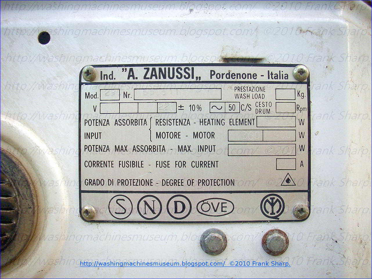

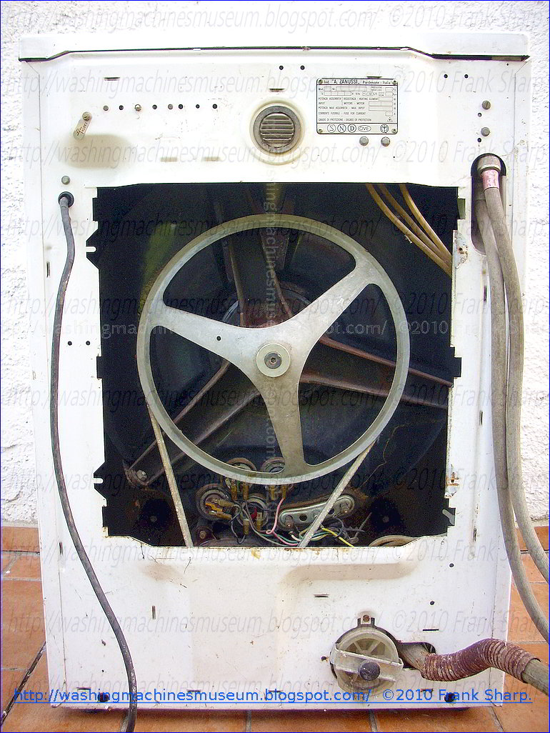


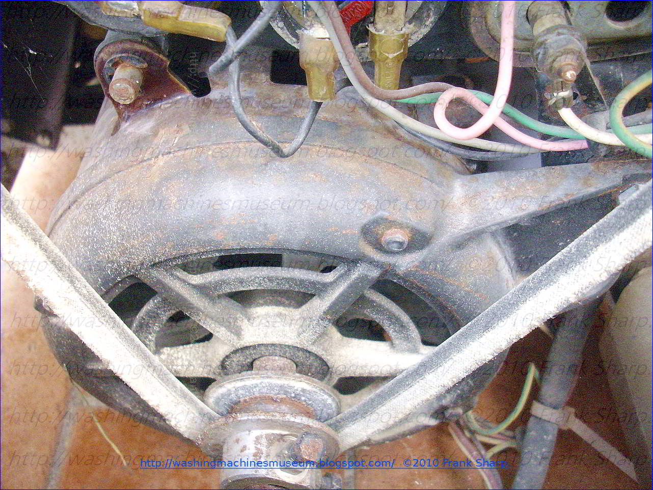


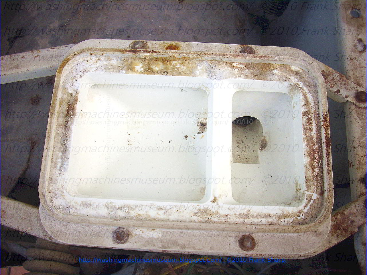


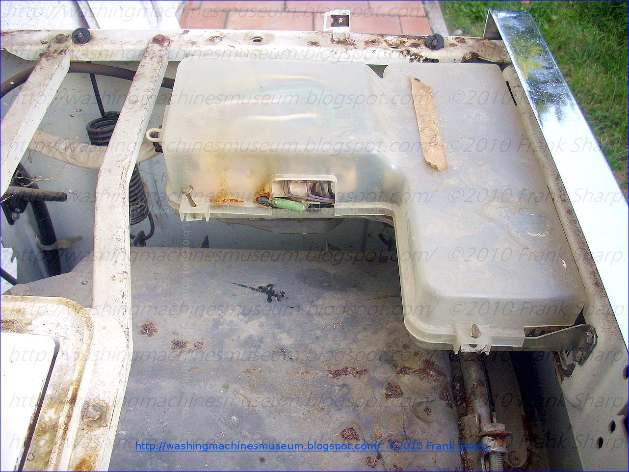


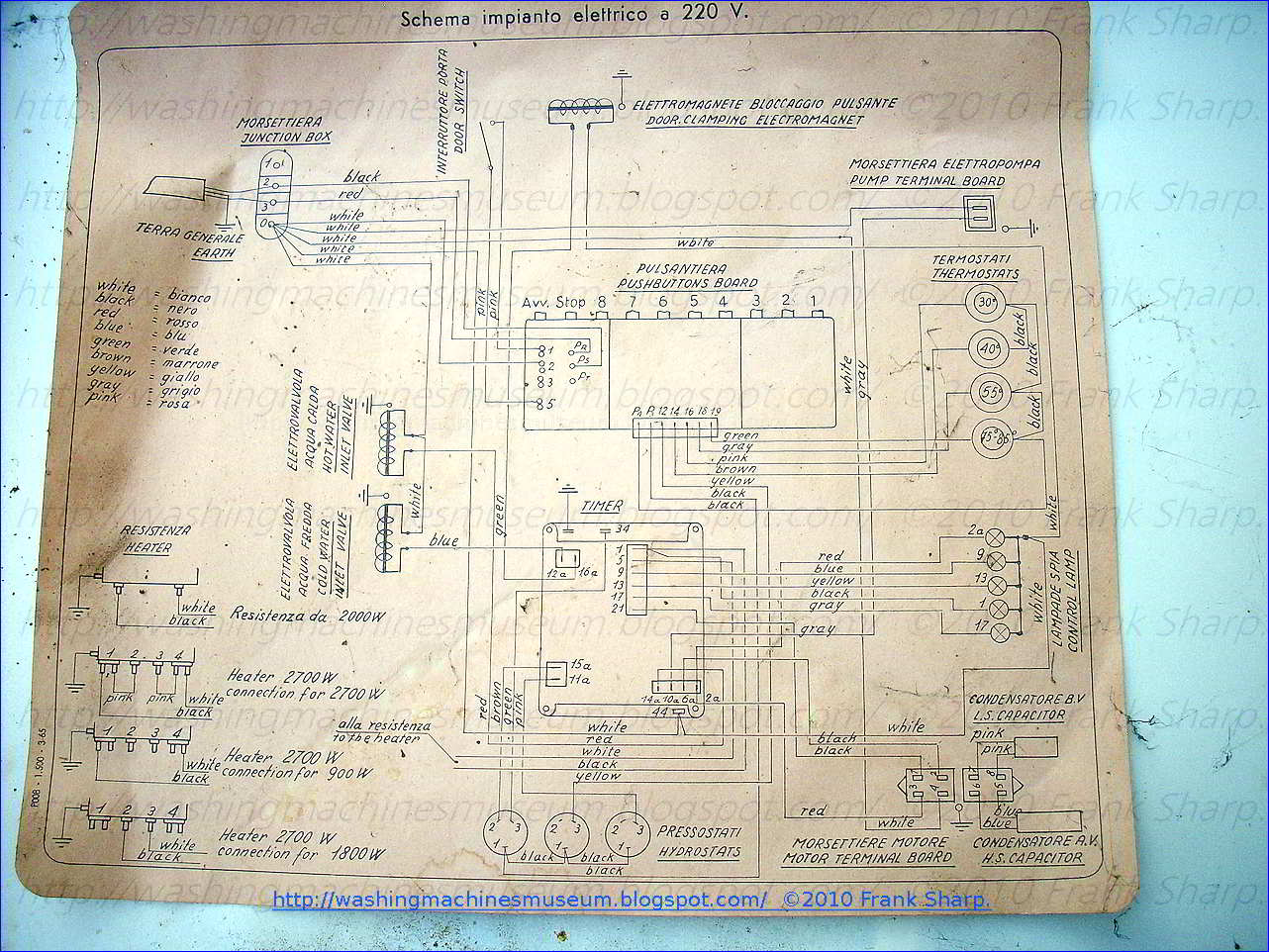


